in this case , I simply don't have second favorite ........ mostly because so long ago I made any comparison so I simply don't care about that anymore to remember
generally , MKP is good
bypassed elco is better than non-bypassed , and 1uF is plenty and you don't need battery of smaller ones
had my share of audiophoolery ........ double-tripple-quadruple share , believe me
tnx to God/Nature/Buddha ....... I don't hear 80% of differences I did heard eons ago

generally , MKP is good
bypassed elco is better than non-bypassed , and 1uF is plenty and you don't need battery of smaller ones
had my share of audiophoolery ........ double-tripple-quadruple share , believe me
tnx to God/Nature/Buddha ....... I don't hear 80% of differences I did heard eons ago
I know what you mean -- sometimes you realise that what you heard last year does not seem to exist anymore...
Anyway, I have a bag full of Wima MKPs in my box, so I will just use those for my headphone Aleph.
Anyway, I have a bag full of Wima MKPs in my box, so I will just use those for my headphone Aleph.

Alright, one more thing...
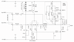
I want to add a volume control to the input of my headphone Aleph. I am planning to use a 4-channel MUSES stepped attenuator (2 x 2 for stereo balanced input). What's the best approach to implement this without upsetting the input stage and the feedback? My idea is in the attachment, but (i) I think it looks too complicated and (ii) it messes up the feedback / AC gain set by the 22.1k and 221k resistors.
Is there a better way?
Attachments
use 10K pots and you're good
Well, how would 10k be better than 20k? I used 20k because the MUSES attenuator I have is 20k.
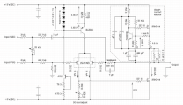
Anyways, my brain was miswired to SE inputs when I made the above drawing. I believe it would be better to avoid the GND reference at the input pot(s). After rebooting the brain I came up with two new suggestions. The first one is automatically balanced and requires only a single pot per channel, but does not allow full 100% volume. The second one allows 100% volume but requires two pots, which need to be perfectly balanced (the MUSES is pretty good).
My brain is still running in circles when I tell it to analyse the effect of the pot(s) on the gain / feedback resistances of the whole amp (22.1k / 221k dividers).
Thoughts?
Attachments
Last edited:
use arrangement from post 644 , with your 20K pots
it'll slightly influence gain behavior , but practically ignorable
it'll slightly influence gain behavior , but practically ignorable
use arrangement from post 644
Why is the version from post 644 preferred over that from post 647? I thought that avoiding the GND connection of the pots would be a good idea.
it would be , in case that I know that you have entire chain fully differential, properly balanced and floating
which nowadays is rarely the case, most output stages being electronically balanced, and often not having equal Rout of phases
though , you can try , and leave option which most suits you , sound-wise and hum-free wise
which nowadays is rarely the case, most output stages being electronically balanced, and often not having equal Rout of phases
though , you can try , and leave option which most suits you , sound-wise and hum-free wise
it would be , in case that I know that you have entire chain fully differential, properly balanced and floating
which nowadays is rarely the case, most output stages being electronically balanced, and often not having equal Rout of phases
though , you can try , and leave option which most suits you , sound-wise and hum-free wise
The source has a transformer output, so it is properly balanced and floating. I just wanted to be sure that I am not missing anything. Changing from one setup to the other will not be difficult, so I'll just give it a try and see.
Oscillation!
So I just finished building the first channel of the amp as shown in post 644. As far as I can tell, the thing almost works. However, the lower MosFET starts oscillating if I turn up the bias voltage.
What I tried so far:
Any ideas what else I could try?
So I just finished building the first channel of the amp as shown in post 644. As far as I can tell, the thing almost works. However, the lower MosFET starts oscillating if I turn up the bias voltage.
What I tried so far:
- Removed the global feedback loop (for easier debugging)
- Tried a larger gate stopper (did not help)
- Controlled the gate from a regulated DC power supply instead of the input/driver circuit (oscillation is the same).
Any ideas what else I could try?
try usual 1nF capacitor cure , 2 positions per channel
Ok, I tried that. Didn't help. I believe it was even a little bit worse.
The only thing that kills the oscillation was to use a different MosFET in the Aleph source. I found an IRFP150 floating around the bench, and tried that (leaving the 2SK214 in the lower position). Oscillations gone!
Are the 2SK214 particularly sensitive to oscillation?
I have to say that I don't understand a thing about those oscillation issues. How do they happen?
well, I didn't catch that detail , that you're using some other mosfet in Aleph CCS
2SK214 there ........
now it seems that I didn't catch anything ...... are you making some mini iteration , with T0220 mosfets?
however..... main problem you had is lower Ugs of mosfet used in Aleph CCS(comparing to IRFP), so small bjt is having lesser voltage window, causing oscillations
no special difference if you use ( even if yuo can without problems) Audio-approved part there, most things are dominated with small bjt and even its job isn't critical
but everything needs to be optimized , as is already in original Papa's concept
well, I didn't catch that detail , that you're using some other mosfet in Aleph CCS
2SK214 there ........
now it seems that I didn't catch anything ...... are you making some mini iteration , with T0220 mosfets?
however..... main problem you had is lower Ugs of mosfet used in Aleph CCS(comparing to IRFP), so small bjt is having lesser voltage window, causing oscillations
no special difference if you use ( even if yuo can without problems) Audio-approved part there, most things are dominated with small bjt and even its job isn't critical
but everything needs to be optimized , as is already in original Papa's concept
See my pre-previous post: I built the amp as in post 644 (here).
Of course I could save the precious 2SK214 and use something cheaper in the Aleph source (and I probably will). But I'd like to understand what's going on with those oscillations. What's the story with that voltage window thing?
IRFP needs approx. 4V for gate being above source , and you have put small bjt in that voltage window
you used 2SK there , which is having half of IRFP voltage ( max 2V ) from gate to source , and you still putting small bjt in that window .... so it's sorta voltage starved
same as when you put sack of cement on your shoulder and need to bring it 100 feet
not so hard, even if boring, if you are walking with your back straight
try the same, while walking through 1.3m high corridor.... after some time you'll have your back snapped, or - in best case - you're going to fight for your breath
same with small bjt ....... he's fighting for its breath, while behaving hysteric (with reason)
transistor demands some minimal rail voltage for at least so-so linear operation
IRFP needs approx. 4V for gate being above source , and you have put small bjt in that voltage window
you used 2SK there , which is having half of IRFP voltage ( max 2V ) from gate to source , and you still putting small bjt in that window .... so it's sorta voltage starved
same as when you put sack of cement on your shoulder and need to bring it 100 feet
not so hard, even if boring, if you are walking with your back straight
try the same, while walking through 1.3m high corridor.... after some time you'll have your back snapped, or - in best case - you're going to fight for your breath
same with small bjt ....... he's fighting for its breath, while behaving hysteric (with reason)
transistor demands some minimal rail voltage for at least so-so linear operation
Ok, I am tall, so I need a bigger tunnel. Makes sense. Which MOSFET would work well? IRF610? IRF530? A TO220 part would be nice so I can re-use my contraption to fix the outputs on the heatsink.
any of IRF small ones you have in drawer, use one with greatest xconductance
I couldn't find a TO220 IRF, so I ordered a few. Left the IRFP150 in there for the moment.
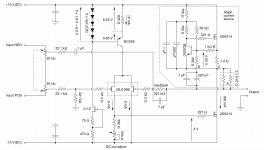
In the meantime I had some fun with the function generator and the scope. I found that the square-wave response was slightly deformed on the falling edge. I don't know what this is, but I could make it go away by inserting a 15 pF capacitor from gate to drain of the gain MosFET (directly on the pins), as shown in the attachment. Any ideas what's going on with this?
(sorry, I forgot to take some screenshots from the scope)
- Home
- Amplifiers
- Pass Labs
- About possible Babelfish J interest