Screens will be supplied at a lower DC voltage obtained from an higher DC source without any AC on it (except ripple, if any), so no feedback on the screens.
Please have a close look: The MOSFETs act as source followers and are driven by the plate signals via voltage dividers. What else would you expect from UL?
Best regards!
Best regards!
Now I got you. I thought you would like to connect the whole circuit to B+, while you want to modulate the 600V through the mosfet by the voltage-divider connected to the plates and ground. Will it work linearly?
I guess so, as cathode, emitter and source followers tend to do. Anyway, this question may arise also if the MOSFET is fed from the plate.
Best regards!
Best regards!
I you want power, better drop the hole idea of UL with lower screen voltage.
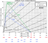
Suppose Vb=600V , Vsc=300V and UL 40%
Now Va swings down to 100V is 600-100=500V on the transformer.
40% of 500V is 200V so the srceen goes down to 300-200=100V
With Va=Vsc=100V Ia becomes 100mA at -Vg1=0, not much current left.
Let's go less deep, swing to 150V , 450V transformer and 300-180=120V for the screen.
Now we get with Va=150V and Vsc=120 an Ia of ~150mA.
What power to expect with those last numbers, 450x150mA/2= 34Wout max 🙁 .
Better stay with 10% cathode feedback if you use lower screen voltage.
Cathode feedback IS UL for the tube, as long as you don't decouple the screen to the cathode.And with the feedback on the tube input there is double benefite.Only drawback, more drive voltage needed.
Mona
Shure, but then don't try to make a B-H with output tubes that don't tolerate high screen voltage.Without UL it is no more baby huey , but Dissitent-audio designed in2004 Push Pull ECL86/6GW8
Mona
Shure, but then don't try to make a B-H with output tubes that don't tolerate high screen voltage.
Mona
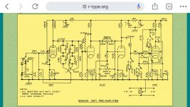
Take a look at this schematic, the Brimar 25P1. The 5B/255M is analogous to an 807 on a Loctal base.
The max screen is 300v, but the B+ is 440v. I just looked more closely at the transformer, and it looks like it must have UL taps, but I can’t be sure of the spec of the original OPTs.
It is quite a highly rated design, so maybe the way the transformer is tapped can make a difference? Each screen has a 390 ohm resistor as well.
Brimar 25P1 25 Watt amplifier
Attachments
Frankly speaking, I always simulated circuits without output transformers, and I've to understand how to implement them.Zintolo,Why you don't use simulator?
Thank you Mona, can I ask you to explain me better these passages?I you want power, better drop the hole idea of UL with lower screen voltage.
Suppose Vb=600V , Vsc=300V and UL 40%
Now Va swings down to 100V is 600-100=500V on the transformer.
40% of 500V is 200V so the srceen goes down to 300-200=100V
With Va=Vsc=100V Ia becomes 100mA at -Vg1=0, not much current left.
Let's go less deep, swing to 150V , 450V transformer and 300-180=120V for the screen.
Now we get with Va=150V and Vsc=120 an Ia of ~150mA.
Datasheet says that maximum power in UL is obtained reaching limits for both plate and screen (of course), so having different voltages on both.
I don't get why you say not to use BH in this configuration. Thanks
Last edited:
This mennovanderveen 300W toroidal 1,6k PP has separate 43% and 10% coils:
Push-Pull : VDV-4140-PP (PAT-4140)
Push-Pull : VDV-4140-PP (PAT-4140)
Take a look at this schematic, the Brimar 25P1. The 5B/255M is analogous to an 807 on a Loctal base.
The max screen is 300v, but the B+ is 440v. I just looked more closely at the transformer, and it looks like it must have UL taps, but I can’t be sure of the spec of the original OPTs.
It is quite a highly rated design, so maybe the way the transformer is tapped can make a difference? Each screen has a 390 ohm resistor as well.
Brimar 25P1 25 Watt amplifier
I think this design is somewhat bold, as the 5B/255M share the ratings with 807.
Best regards!
When you are talking about putting 600V on the anodes with 300V on the screen to get much power the trouble starts.The greater the difference between anode and screen voltage the worst UL goes.Thank you Mona, can I ask you to explain me better these passages?
Datasheet says that maximum power in UL is obtained reaching limits for both plate and screen (of course), so having different voltages on both.
I don't get why you say not to use BH in this configuration. Thanks
With 450V and 300V screen it's not too bad, can still get ~50W but with 600V anode and 300V screen you get only ~35W, the 40%ΔVa gets to much for the 300V making the screen voltage very low.
Mona
Attachments
Rather odd, makes a effective 53% UL if both are used.This mennovanderveen 300W toroidal 1,6k PP has separate 43% and 10% coils:
Push-Pull : VDV-4140-PP (PAT-4140)
He made an VDV-2100-CFB with 33% and 10% total 43% UL.
And a VDV-4070-CFB with 33% and 7,1% giving 40,1% UL.
Mona
Rather odd, makes a effective 53% UL if both are used.
He made an VDV-2100-CFB with 33% and 10% total 43% UL.
And a VDV-4070-CFB with 33% and 7,1% giving 40,1% UL.
Mona
Hi Mona,
can that configuration be used with positive CFB, to obtain a pentod-er UL at 33%?
I remember this post of gingertube talking about different configurations used in hi-fi:
43% of voltage (hence also number of turns) has been the accepted "standard" for Ultralinear taps. If you go back and start researching the beginnings of Ultralinear you will find that 43% is the optimum minum distortion configuration for EL34 tubes (20% for max power). Also appropriate for EL84. Once you start talking about other tubes then other ratios actually apply but since these are hardly ever documanted folks just assume that 43% will suit every tube.
An old paper by Fritz Langford Smith (Editor of Radiotron Designers Handbook) suggests 5 to 10% is what best suits 6V6. I have seen seen at least one KT88 amp which used 50% taps.
Next you state you want to combine cathode feedback and ultralinear. The thing to recognize here is that the Ultralinear feedback is the voltage applied between screen and cathode. If you apply 10% NEGATIVE cathode feedback then the ultralinear taps will want to be around 30% to give you the same Ultralinear operation as 10 + 30 = 40%.
If you look at Plitron VDV2100 CFB/H Torroidal Output Trannies (for example) you will see that it offeres exactly this, 10% cathode feedback windings with UL taps at 30%.
They also have a 2100-SSCR which is 40% Ultralinear in a separate winding.
There are a few weird arrangements around, probably the weirdest is the Jadis JA80 (4 x KT88 in Class A for 80 Watts) which uses about 50% Ultralinear with 10% POSITIVE cathode feedback to arive back at the approximately 40% point again.
If you want the Fritz Langford Smith articles (From Radiotronics Magazine) send me a PM. They would be too big to post here (approx 500KB). They were in 3 parts, a quick google of "Radiotronics Ultralinear" suggested that a couple of the parts may be available on some sites.
Cheers,
Ian
Frankly speaking, I always simulated circuits without output transformers, and I've to understand how to implement them.
If you want ,I can model for you in Tina . As the governor closed the beach ,I am Tooo bizy doing nothing.
Last edited:
When you are talking about putting 600V on the anodes with 300V on the screen to get much power the trouble starts.The greater the difference between anode and screen voltage the worst UL goes.
With 450V and 300V screen it's not too bad, can still get ~50W but with 600V anode and 300V screen you get only ~35W, the 40%ΔVa gets to much for the 300V making the screen voltage very low.
Mona
Thank again Mona, and sorry for asking things that may seem dull.
Does the g3 positive voltage improve the curves in this scenario (I think you have seen the thread I've posted above), or it is just needed to find a tube that can accept high plate and screen voltages?
I copy here a message by gingertube, to be used to define the details of the PI.
As you can see, every quote I add here has internally a link to go to the original discussion.
As you can see, every quote I add here has internally a link to go to the original discussion.
There is a trade off between getting the 12AX7 current higher and the anode voltage dropping due to increased voltage drop across the anode resistors.
About 1.2mA (that is 0.6mA each side of the diff amp) is a good value but 1.0 or 1.1mA would be OK.
If the anode voltages on the diffamp are less than say 140 Volts then decrease the CCS current a little. If the anode voltages are above say 190 Volts then you can increase the CCS current a little.
The way to think about this is ( for example)
The Output EL84s are going to need +/- 12V signal swing, so that is what has to appear at the differential amplifier (diff amp) anodes.
The feedback voltage appears 180 degrees out of phase at the other end of the 220K anode load resistor. Say we have +/- 24 Volts of feedack signal at that point (depending on the size of that cross coupled feedback set resistor). We would then need to develop a total of +/- 36V across the 220K load resistor which means we have to swing 36/220K = +/- 0.164 mA current through each triode of the diff amp. In that case 0.5mA would be OK - the current would swing down to 0.336mA and up to 0.664 mA. Output may be a little cleaner (less distortion) with 0.6mA idle current as it doesn't swing as close to 0 current where the worst non-linearities are BUT the distortion is mostly second harmonic and the diff amp action will take most of that out, I don't think it will make a lot of difference.
So while you will nearly always see 12AX7 operated at higher idle currents than this (typically more like 1mA) in this circuit 0.5mA to 0.6mA is fine and that helps keep the anode voltage at reasonable levels.
From the above you can also see that it is possible, if you use really high values of resistor for that cross coupling feedback set resistor, that eventually the 12AX7 would try to swing down to 0 current. I've found that about 47K or 56K are the practical limits on its value but I never liked the sound with any of those really high values. Around 15K to 20K sounds good - up to 33K can sound OK depending upon how "tight" and "neutral" you want the amp to sound. At 47K the amp sounds transistor-ish (those 3 legged fuse things) and is quite dull, sterile and boring.
Hope this "explaination" helps.
Cheers,
Ian
This is the memorandum of the post concerning the common resistor on cathodes to reduce THD and IMD (plots can be see in the two posts before on the original thread):
Sheldon,
Thanks for your feedback.
The Baby Huey with approx 40mA current sources in the output tube cathodes is roughly equivalent to running 270R cathode bias resistors.
Based upon the 0.13 or 0.14 ratio that would suggest using a 36 Ohm resistor. Notes I have from another source say the null is reasonably broad so 33 or 39 Ohms would do.
Cheers,
Ian
- Home
- Amplifiers
- Tubes / Valves
- Baby Huey enters into puberty: 6550 KT88 possibly GU50?