Your contribution to the thread would be really appreciated. If you would like to explain briefly how to do it, it would be great too. Thanks!If you want ,I can model for you in Tina . As the governor closed the beach ,I am Tooo bizy doing nothing.
Rather odd, makes a effective 53% UL if both are used.
He made an VDV-2100-CFB with 33% and 10% total 43% UL.
And a VDV-4070-CFB with 33% and 7,1% giving 40,1% UL.
Mona
Rather odd, makes a effective 53% UL if both are used.
He made an VDV-2100-CFB with 33% and 10% total 43% UL.
And a VDV-4070-CFB with 33% and 7,1% giving 40,1% UL.
Mona
Mona, I wrote wrong 43% when I have searched Toroidy OPTs lately which usually have 43%
That VDV transformer seems to have separate 40% and separate 10% coils and when on Robertos first post he wanted a separate 40% winding. Then later he wrote that Toroidys could not be made powerful enough but that Mennos design is 300W at least "on paper" but weights 4.6kg as well 😉
I can see your discussion has changed and it is not what I fully understand yet...
I bought VDV-4050-Guitar push pull OPT because it is very light only 984g but it takes one or two weeks until I get its circuit finished. I already have VDV-2512-SEE on guitar amp and it sounds very good.
I know concern that some or all PP toroids are prone to saturate if circuit gets unbalanced.
Esa
Last edited:
I've found this thread that is a good starting point for the GU50, bypassing g2 limits of other tubes:
First let us have a look to the tube itself. It is a “real old style pentode”; the screen grid (G2) is not in the shadow of the control grid as in beam power pentodes. What is the consequence? If the plate voltage is lower than the G2 voltage than the G2 current in much higher than in a beam power pentode like KT88. Taking into account the maximum allowed G2 power dissipation we can expect a lower maximum G2 voltage than e.g. for a KT88. Looking to available application data from LS50, E/FL152 and GU50 (they are all the same type of pentode except for the heater voltage) here are some observations which confirms this assumption:
In PP pentode mode up to a plate supply (Ub) of 400V the G2 voltage (Ug2) is limited to 250V In PP pentode at Ub=600V/800V Ug2 is limited to 300V In PP Triode mode Ub= 400V is allowed
In a LS50 report there have been shown static data values for triode mode with Ua/Ug2= 800V
Some conclusions/observations
For higher Ub (basically > 300V) we need a separate UL winding for G2) Ug2 up to 800V is possible
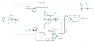
Using these constraints I have made a test circuit with a PP UL OT having a separate screen winding (20%/40%). MOSFET drivers allow to drive the powerstage with AB2. The plate supply (Ub) is 800V, the screen supply is switcheable between 400V and 600V.
Case 1) (moderate)
Ub=800V, Ug2=400V,Raa 7K8,UL=20%, AB2 with NFB. The output power is about 120W.
G2 is not going red what I have expected. The first scope picture is showing the result:
- at the upper scope : Ug1 and Output at 7,8 Ohm
- at the scope below: Ua and Ug2
You can see on the scope picture the voltage ratio between the plate voltage (Ua) and Ug2 caused by the UL mode. The duration of Ua <Ug2 is limited, as well as the voltage difference.
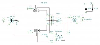
Case 2) (aggressive)
Ub=800V, Ug2=600V,Raa 7K8,UL=40%, AB1 with NFB. The output power is about 120W.
A scope picture and a distortion measurements are attached. Again G2 is not going red, as long as we are at AB1. (Ug1max=0V). I have done some “duration tests”, several hours running at full power. The power stage has shown stable behavior.
I personally might use case 1) in a bass amp and case 2) in hifi applications. I know that an UL OT with separate G2 winding has some obstacles (cost, complexity etc…).
And this comment of gingertube to scale down the feedback from screens compared to the one from plates:
Instead of taking the shunt feedback from the EL84 Anodes I changed it to take the balanced shunt feedback feeds from the Ultralinear Taps.
The Ultralinear Taps have 43% of the AC Voltage on them and also have a lower "drive" impedance. If anode to anode load is 8K then the maths say that the screen tap to screen tap drive impedance is 1500 Ohms.
Instead of 47K from each EL84 anode and 16 K as a cross connect to set feedback level I used 10K from each screen tap with a 9K1 (2 x 18K in parallel would do)as the cross connect. Measurements confirmed this gave identical feedback levels, sensitivity and output impedance.
That meant 20 V less DC drop in the feeds to the diffamp and I was able to increase the diff amp current by 100uA per side (Current Source upped by 200uA, that is, the CCS which was 1.2mA is now 1.4mA).
The increased diff amp current and the output transformer now being partly within the feedback loop I thought, gave worthwhile improvement. The sound seems a little better balanced across the frequency response. With the feedback off the EL84 anodes I thought frequency response was a little peaky at the high and low frequency extremes.
I also thought that detail was perhaps a little better.
In what you quote from es345 it shows he had to bring the UL back to 20% with an great difference Ua(800V) and Ug2(400V) to prevent the g2 to go to low for keeping enough Ia.
Ones he goes upto 600V Ug2 he can use 40% again.
Mona
Ones he goes upto 600V Ug2 he can use 40% again.
Mona
Thanks Mona, the problem with GU50 is their low gm, for this specific application.
Without shunt feedback, he used pentodes as PI due to the increased drive the PA needed.
Without shunt feedback, he used pentodes as PI due to the increased drive the PA needed.
I would like to link some articles of mid-1955 about UL by Langford-Smith, where he suggests caps between plates and screens, not usually implemented in UL design:
https://frank.pocnet.net/other/AWV_Radiotronics/Radiotronics_1955/1955_05_AWV_Radiotronics_20_05.pdf
=https://frank.pocnet.net/other/AWV...onics_1955/1955_06_AWV_Radiotronics_20_06.pdf
=https://frank.pocnet.net/other/AWV...onics_1955/1955_07_AWV_Radiotronics_20_07.pdf
https://frank.pocnet.net/other/AWV_Radiotronics/Radiotronics_1955/1955_05_AWV_Radiotronics_20_05.pdf
=https://frank.pocnet.net/other/AWV...onics_1955/1955_06_AWV_Radiotronics_20_06.pdf
=https://frank.pocnet.net/other/AWV...onics_1955/1955_07_AWV_Radiotronics_20_07.pdf
Last edited:
Three articles about CCS:
https://audioxpress.com/assets/upload/files/Sources_101_P1.pdf
https://audioxpress.com/assets/upload/files/Sources_101_P2.pdf
https://audioxpress.com/assets/upload/files/AX_Letters_0907.pdf
Last link contains what seems one of the best solutions, the single Vbe at page 59.
https://audioxpress.com/assets/upload/files/Sources_101_P1.pdf
https://audioxpress.com/assets/upload/files/Sources_101_P2.pdf
https://audioxpress.com/assets/upload/files/AX_Letters_0907.pdf
Last link contains what seems one of the best solutions, the single Vbe at page 59.
Some other tips by gingertube on another forum:
Grid stoppers with AB21) Choose the Drain Voltage such that on the maximum positive signal swing on the gate and hence also on the source you have at least 25 to 30V left across the mosfet drain to source. This effectively minimises any modulation of the device capacitance with the audio signal. Probably not critical in a MI Amp but quite noticeable in the smoothness and detail of the top end in a HiFi Amp. No point in going higher on the drain voltage, all that does is increase the power dissipation in the mosfet.
2) Don't use huge power mosfets, I use ZVN0545A (600mW) when I can or a 2 to 5 Watt rated device when the 600mW is'nt enough.
3) Direct couple the mosfet source to the output tube grid with just the grid stop in the path
4) Apply the output tube bias to the mosfet gate.
5) Dont forget the protection zener (12 or 15V) between gate (zener cathode) and source (zener anode). Right on the mosfet gate and source pins.
6) DO use a gate stop on the Mosfet, 220 Ohms to 1K will do, Mosfets have lots more gm than tubes and accordingly are even more prone to parasitic oscillations because of it.
7) The source load resistor should return to a negative rail of at least 3 times the output tube bias voltage (rule of thumb).
8) If you want to go a little overboard (or if you are building a HIFi Amp) replace the source follower load resistors with current sources, they don't need to be particularly great current sources, the "Ring of Two" bipolar transistors works very well, a high beta, garden variety small signal BC548C for example on the bottom with an MJE340 above it for 300V withstand is what I routinely use. Th Current Source Loads do sound better than simple resistive loads but again that is my HiFi Amp experince talking. You may not notice the difference with a MI Amp.
OH! and do remember to fit the output tube screen resistors with the resistor body right up against the tube socket pin, just like you do for the grid stop. Screen resistors have a grid stop function as well as their screen dissipation limiting function.
This arrangement (source follower drive of the Output tube grid) give one huge benefit which is very often overlooked. Output tubes suffer from a fair amount of grid current noise (random grid currents). With the low impedance drive of a source follower, this noise current is shunted to signal ground and the amp is MUCH quieter. HiFi Amps I've built using this scheme have the "blackest" background of just about any amp I've ever heard, tube or SS.
The model GU50 is not precise but the circuit is working.
Attachments
Last edited:
Thanks Mona, the problem with GU50 is their low gm, for this specific application.
Without shunt feedback, he used pentodes as PI due to the increased drive the PA needed.
Yes. We mustn't forget that GU-50 is based on a really vintage design. It is, as yte mentioned multiple times, more or less a direct copy of TELEFUNKEN's WWII LS-50 power pentode. But this yet had a predecessor, the RL 12 P 50 (sorry, available only in German language) from the very early 1940ies.
Compared with e.g. the EL 34, it needs one and a half times to twice the drive voltage plus grid current (i.e. a low impedance driver) for almost the same output power.
Best regards!
B-H and GU-50 is not a good mix. Nor is UL with low Vg2 and unchanged tap%.
If you need more power with the B-H use EL34 or EL156 and Vb=500V.
Mona
If you need more power with the B-H use EL34 or EL156 and Vb=500V.
Mona
How long do you think the screens will survive that 😱By applying a positive feedback of 6% on g2 , it is possible to get 75w 2.5% Dtot. If 2 pairs of these low cost tubes (3 euro) is used, 100w 1% is at reach.
Mona
How long do you think the screens will survive that 😱
Mona
On simulator I get average screen current of 11.9 ma, for 75w output. This makes 11.9ma x250v =3W. With g3 14v , the screen current is lower.
Perhaps at 75W it's still acceptable.But when the anode goes realy low the screen current goes up dramatically especialy with the higher voltage caused by the pos fb.On simulator I get average screen current of 11.9 ma, for 75w output. This makes 11.9ma x250v =3W. With g3 14v , the screen current is lower.
Mona
I am not the one who is designing this amp. I just made a quick feasibility to see if 2 pairs of gu50 can provide 100w with low distortion.
Depends on how we define low distortion. According to the EL/FL152 datasheet, both also direct successors of the LS 50, up to 120 watts are obtainable from a pair of these tubes, at 10 % THD, though. See page 9. With 20 dB NFB 1 % THD aren't out of reach. Beware: This is AB2, so a low impedance driver is mandatory.
Best regards!
Best regards!
By using a more precise model from Nakabashi Tube Models for TINA , I get 70W with 0.8% distortion Ig2=7.4ma average. The bias -35v for Ip46ma (too high) input +/-35vp. Of course it needs fine adjustments.
Attachments
The model GU50 is not precise but the circuit is working.
Shokran kokoriantz, I see there's no g3 there, that from what I've seen is very important to optimize the curves. I will take a deeper look at it tomorrow.
- Home
- Amplifiers
- Tubes / Valves
- Baby Huey enters into puberty: 6550 KT88 possibly GU50?