PSU with Active rectifiers
Hi Xrk,
Request you to share more details(or link) on active bridge recifiers..wish to learn more about it.
Thanks
Hi Xrk,
Request you to share more details(or link) on active bridge recifiers..wish to learn more about it.
Thanks
Nice compact layout, Prasi! We could use the active bridge boards for the rectifiers. Even for Class AB, I have found that an LT4320 reduces the diode switching noise, and really, eliminates the need for the snubber. This is all possible because the switching is at zero-crossing vs 0.6v (Si diode switching), hence no noise generated. This results in a cleaner or "blacker blacks" noise background. Your GBJ format active bridge boards are perfect for this. The only issue is added expense of a $7 LT4320 chip x 2, plus nominal cost of the active bridge board.
Just pointing this out as I have noticed a substantial improvement in sound quality, even with non Class A amps whne LT4320 is part of the PSU.
Hi Xrk,
Request you to share more details(or link) on active bridge recifiers..wish to learn more about it.
Thanks
I think X is talking about this small compact LT4320 based rectifier boards - https://www.diyaudio.com/forums/group-buys/336572-lt4320-based-active-rectifier-74.html#post6154186
Hi, good to see this thread is still in use. Has anyone built the A-10? maybe...made a PCB they would like to share?
differences with psu10 sir
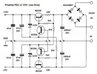
PSU10 voltage regulators require a large voltage drop between the input and the output to function correctly. This requires a relatively high-voltage input power supply and results in low power efficiency. PSU10R low drop linear voltage regulator is a type of linear voltage regulator circuit that works well even when the output voltage is very close to the input voltage, improving its power efficiency. There is +/-15V low drop regulator for preamps.
Attachments
Just pointing this out as I have noticed a substantial improvement in sound quality, even with non Class A amps whne LT4320 is part of the PSU.
Thanks X,
Another amp I wanted to build was your FH-9 . Have you powered your FH-9 with LT4320?
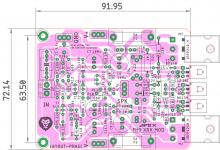
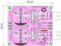
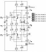
I wanted to have film cap at input and somewhat spacious layout, so here is modified version of FH-9 layout.
regards
prasi
Attachments
PSU10R
Is this psu work on 40 volts ac.any change need.
Regards
Gurpreet
Is this psu work on 40 volts ac.any change need.
Regards
Gurpreet
Yes, no changes from 2x40v AC to 2x70v AC.
Regulator output voltage start from 45V DC to the input voltage if you need lower voltage change 15V zeners to 12V and regulator start from 36V output voltage to the input voltage (55V with 40v AC transformer).
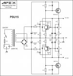
PSU15
Quick draw McGraw
Attachments

Last edited:
Thanks X,
Another amp I wanted to build was your FH-9 . Have you powered your FH-9 with LT4320?
I wanted to have film cap at input and somewhat spacious layout, so here is modified version of FH-9 layout.
regards
prasi
Nice layout Prasi, I like the idea of fuses on both sides. If you are printing out I would like to have a pair of these boards.
Thanks
Quick draw McGraw
Gun on your hand ever! 😉
Very good work doctor pcb!!!
I had the old FH9HV amp boards which were damaged last year during my setup. I have some issues with one of the amp boards. The other one works perfectly with 50mV bias and offset being 0.2mV.
1. Now with some free time I tried to revive the bad board and found that during my initial setup the ground connection from the input ground to the power ground was burnt up. Literally the ground trace was burnt up and I did some solder paste and was able to connect the ground planes and checked the continuity.
2. Then after I powered it up I realized that the 0.47R 5W resistors were glowing red hot and immediately switched. Realized that the 220R resistor near the 9240 mosfet was burnt. Replaced the resistor and checked all the transistors. Found that the 9240/240 both were damaged as on the DMM it was showing as shorted.
3. Replaced both the transistors and rechecked for the BD139/140 as well and all seems to be fine.
4. Now when I powered it back again with one DMM on the legs of one of the 0.47R 2W resistors for bias and another output+ground for offset. Here are the values I am getting with the trimmer being at the lowest.
Bias - 740mV
Offset - 0.9mV
How much ever I turn anti-clockwise direction the trimmer the bias is not getting reduced. The offset fluctuates between 0.0-3.5mV. But when I turn the trimmer in clockwise the bias increases in couple of turns itself and jumps close to 1V. Not sure what could be the issue as every other resistor/diode/caps seems to be fine.
I am running them with 4 secondaries of 30v 2.5A transformer each amp board powered by a capMX psu which gives roughly 42vdc. Here are some pics for reference of the bad board.
As you can see from the first pic one of the legs was not soldered properly from the top of the board. I did reflow the solder from top but still the same issue of unable to drop the bias from 750mV. Seems to be some resistor issue in series with the trimmer not working to reduce the output bias.
I think someone can guide on this issue.
Thanks
I think someone can guide on this issue.
Thanks
Hi Mr Miles,I made this amplifier for test my home DIY speakers (two way TL).
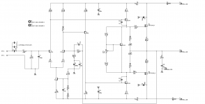
D4 on component layout wrong polarity, in post #253 is corect componenet layout.
Can i replace Q7 with Bc546? It will work or burn?
Quick draw McGraw
Nice Prasi, what about PSU10R, MOSFET not available in area.
As you can see from the first pic one of the legs was not soldered properly from the top of the board. I did reflow the solder from top but still the same issue of unable to drop the bias from 750mV. Seems to be some resistor issue in series with the trimmer not working to reduce the output bias.
I think someone can guide on this issue.
Thanks
Hi Manniraj,
Always use a mains bulb tester in series with your mains. That way damage is not done even if there is short. Sudden jumping of bias could indicate oscillation. pl check if there is a sim file with which you could check voltages at various junctions to identify the issue..
I am thinking of making FH-9 pcbs and will let you know when they are done... Although its gonna take time considering current situation.
regards
prasi
- Home
- Amplifiers
- Solid State
- 100W Ultimate Fidelity Amplifier