Hi, all,
I constructed several Class AB amps before but never construct a real Class A amp, it is because Class A amp needed big heatsinks and high volume of power supply caps stop me.
Now I start planning to construct a 20W Class A amp, I want to use a pair of TO-3 power transistor 15023/15024(I have stock) per channel.
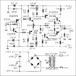
The reference Amp are Musical Fidelity A1 and Jean Hiraga 20W, I prefer Jean Hiraga amp more.
The Class-A Amplifier Site - Hiraga 20W Class-A
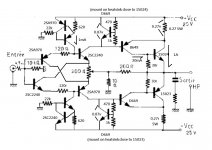
I want the amp with temp stable and balance in performance. For the Jean Hiraga schematic, I changed the 9v zener diodes to a transistor current source, I think it is more easy to matching 2 channels difference than using zener diodes, I changed the thermal resistor control to a Vbe multiplier and install it near the power transistor to compensate the temp.
I don't know how to use those simulation software, please help me and advice if the above change is suitable or having good ideas to construct the amp.
Thanks,
Patrick
I constructed several Class AB amps before but never construct a real Class A amp, it is because Class A amp needed big heatsinks and high volume of power supply caps stop me.
Now I start planning to construct a 20W Class A amp, I want to use a pair of TO-3 power transistor 15023/15024(I have stock) per channel.
The reference Amp are Musical Fidelity A1 and Jean Hiraga 20W, I prefer Jean Hiraga amp more.
The Class-A Amplifier Site - Hiraga 20W Class-A
I want the amp with temp stable and balance in performance. For the Jean Hiraga schematic, I changed the 9v zener diodes to a transistor current source, I think it is more easy to matching 2 channels difference than using zener diodes, I changed the thermal resistor control to a Vbe multiplier and install it near the power transistor to compensate the temp.
I don't know how to use those simulation software, please help me and advice if the above change is suitable or having good ideas to construct the amp.
Thanks,
Patrick
Attachments
Last edited:
The NTC compensates the driver's Vbe termal variations , not the outputs. The voltage multiplier over compensates and shunts very low impedance .
The NTC compensates the driver's Vbe termal variations , not the outputs. The voltage multiplier over compensates and shunts very low impedance .
Thanks, understood.
Is it means that the Class A amp power transistors temperature no need compensate as a Class AB amp?
The VBE multipliers is a very bad idea. You are reducing the open loop gain heavily without really gaining something.


The VBE multipliers is a very bad idea. You are reducing the open loop gain heavily without really gaining something.
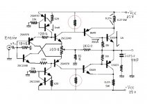
Ok, I got your meaning. I will remove the VBE multiplier and change back to resistors.
I saw there is a thermal resistor in the schematic and I saw one Class A amp project which attach a thermal resistor to the output MOSFET, I though this a kind of thermo control, so that raise this idea of using a Class AB amp VBE multiplier here.
Thanks,
Patrick
Thats the unmodified version
below is the more usual build
quite different
I use a current source to replace the zener diode is according to another thread "Jean Hiraga Super Class A 30w Build" which also using a current source. There is a schematic inside this ebay kit.
Hiraga super 30W class A w/ current source + kubota reg partial assembled kit ! | eBay
The rest of the circuit will be constructed very close to the original version.
Thanks,
Patrick
Attachments
- Home
- Amplifiers
- Solid State
- Construction a 20W Jean Hiraga class A amplifier advice needed