Here's a fully "automatic" version. All one has to do is change the Frequency parameter. Plotting, fft-ing, fourier-ing are all taken care of with no other changes and no glitches at any frequency.
Enjoy.
Thanks. I'll have a play around with your file and try and apply it to others I have. Haven't opened it yet
")
Mooly
In LTSpice component values the units are ignored so an inductor with a value of 1H is the same as one with a value of 1. However in the case of capacitors "F" means "femto" so 1F is 1E-15 Farads (not 1E-9). Another gotcha that trips up a lot of people is that "m" and "M" both mean milli, for 1E6 you use "Meg".
As far as your Fourier issues are concerned unfortunately I don't have time to run the sim today but my *guess* is that you're not in steady state. Fourier analysis doesn't make any sense if the simulation is changing state. That's why I always run a .tran analysis first to understand the time behavior before I do an ac analysis. Then I set the simulation to not collect data until steady state is reached.
tommost
Thank you
The 1F had me stumped when I first encountered it as I could then change it say 999,999uF (anything) and get the expected result. But not with 1F. I needed my memory jogging on that one.
I'll look at the glitchy result and again although I did let the sim run a while and only collected the last part of the data. Nothing seemed to make any difference at the time.
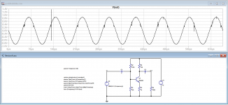
Last shot shows the glitches at 12k. Why ?
I've been looking into this. Using the attached VersionA.asc, in which both capacitors have been changed to a value of 1, the glitches certainly appear at 12kHz, see Fig1.png. At first sight the glitches do not appear at 10kHz or 15kHz, but in fact if you zoom in it is possible to see that the waveforms are pretty rough, see Fig2.png, (15kHz zoomed in).
Things improve if either C1 or C2 is made 1uF, but zooming in still shows anomalies - look at the currents in the capacitors.
Having experimented with "longhand" versions, "automatic" versions, and various time steps and capacitor values, I think the reason for the glitches is that we are asking too much from the maths engine of LTspice. If the parameter fft is reduced from 2**18 to 2**12, everything snaps into place - the glitches at 12kHz disappear, and the FFT plot looks fine. See VersionB.asc. Because the time step is now larger (don't forget that parameter fft is in the denominator of the time step) the simulation runs much more quickly, too.
Because increasing the value of parameter fft decreases the maximum time step, one would expect that larger values of fft would increase the resolution and accuracy of LTspice. However, there is clearly a limit to how far we can push the programme.
And to answer your question: why are the glitches worse at 12kHz that at 10kHz? I think the answer may lie in the fact that 1/12k is an irrational number. So when we define the start time and stop time in terms of the frequency, they too are irrational numbers. Compare this to 10kHz, when a start time of (say) 2/10000 becomes almost trivial. It seems LTspice can work more cleanly with, for example, a start time of 0.0002 than it can with 1.6666666666666666666666666666667e-4.
There is some supposition here, but I think this is on the right track.
Attachments
Last edited:
Having made very good progress in learning the basics of the application and how to avoid the pitfalls, with great help from yourself and others, I really need to learn how to add some toobe models. I have discovered a treasure trove of tube models by Ayumi Nakabayashi, but cannot find a clear well-explained method for adding them to LTSpice XVII. All the tutorials from LT or Analog Devices for adding any sort of model are far too advanced, and require a thorough knowledge of the application's syntax. The others are either word-for-word copied, or cobbled together by folks with no clear knowledge (just click-bait sites). There must be surely a method for doing this on these pages but I'm boggle-eyed from searching. Maybe someone would direct me to the info. Thanks.Pleased you are finding it useful. Tooobs... no promises (and I don't do tooobs
Last edited:
Well, I'll be jiggered, there is a tutorial section on page #85.Maybe someone would direct me to the info. Thanks.
I really need to get out more - oops, I can't; mandatory Covid-19 confinement.
Last edited:
I'm just seeing if I can cobble something together for this... LOL I don't do valves
Have you seen this that kevinkr did a while back:
LTSpice Triode "Unknown subcircuit"
Have you seen this that kevinkr did a while back:
LTSpice Triode "Unknown subcircuit"
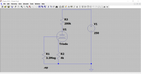
Lets start with a sim called 'Triode Test'.
LT already includes symbols for triodes and pentodes and tetrodes and so lets place the triode symbol on the workspace. They are found under [Misc] in the component selector.
Now what... lets take a really simple circuit and I'm having to think valve now and not solid state. This looks in the right ballpark value wise. I'm making it up as I go along.
Lets set a .op command and run it... and of course it reports an error because the triode is just a symbol with nothing attached to it to specify how it behaves.
LTSpice Triode "Unknown subcircuit"
Download and extract the files. Open each folder and copy the file/folder in each and then paste that in the appropriate folder of LT.
Use the folders that LT XVII places in Documents, not the ones in the Program Files location.
While you have the tube.lib file copied to your clipboard you can also paste it somewhere else as well (anywhere) and then rename it to tube.txt
That will allow you to open it and view all the files in notepad.
Now add the directive 'include tube.lib to the simulation.
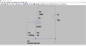
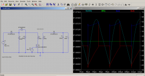
Now we pick a triode to test... 12AU7 maybe... and see what happens.
All looks good, the sim runs and the DC conditions look about right.
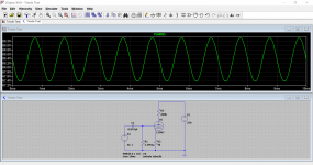
Lets try an AC sim and add a signal source. How is that, it works. I just made a valve amp.
Thanks to kevinkr for those files.
LT already includes symbols for triodes and pentodes and tetrodes and so lets place the triode symbol on the workspace. They are found under [Misc] in the component selector.
Now what... lets take a really simple circuit and I'm having to think valve now and not solid state
. This looks in the right ballpark value wise. I'm making it up as I go along.Lets set a .op command and run it... and of course it reports an error because the triode is just a symbol with nothing attached to it to specify how it behaves.
LTSpice Triode "Unknown subcircuit"
Download and extract the files. Open each folder and copy the file/folder in each and then paste that in the appropriate folder of LT.
Use the folders that LT XVII places in Documents, not the ones in the Program Files location.
While you have the tube.lib file copied to your clipboard you can also paste it somewhere else as well (anywhere) and then rename it to tube.txt
That will allow you to open it and view all the files in notepad.
Now add the directive 'include tube.lib to the simulation.
Now we pick a triode to test... 12AU7 maybe... and see what happens.
All looks good, the sim runs and the DC conditions look about right.
Lets try an AC sim and add a signal source. How
is that, it works. I just made a valve amp.Thanks to kevinkr for those files.
Attachments

Thanks. I've done 15 hours on LTSpice now today. I'll attack it all bright-eyed and bushy-tailed again tomorrow. Thanks once more.I'm just seeing if I can cobble something together for this... LOL I don't do valves
Have you seen this that kevinkr did a while back:
LTSpice Triode "Unknown subcircuit"
Time now to crank up my 1930s designed 300B SET (that's a tooob amp BTW) and play some 1960s John Lee Hooker. The title track is called "It Serve You Right to Suffer".
 .
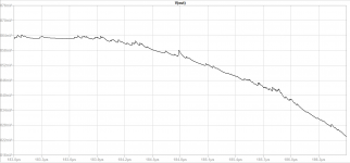
.I am 'trying' to simulate a very basic switching power supply without regulation. The attached image is what I am getting. I am also attaching the .asc schematic. Please, note the schematic is not a real power supply, but a ficticious one.
I am posting for possible suggestions.
V(n005) is the voltage across the 100R resistor.
I am posting for possible suggestions.
V(n005) is the voltage across the 100R resistor.
Attachments
I'm going around in circles. I'll try and outline my problem.
The important things I found were to extract the files first, and then open each extracted folder in turn copying and pasting the contents to the correct location.
There are only two items in all to copy and paste.
Tubes_sym.zip contains a folder called "Tubes_sym". This contains a folder called "Tubes". This contains four folders called "Diodes" "Pentodes" "Tetrodes" and "Triodes". Each one of those contains a selection of .asy files; in other words, a selection of files within four individual folders, within a folder within a folder, all within the .zip folder.
tubes_lib.zip contains a folder called "tube_lib". This contains one file called "tube.lib"
The bottom line here is that I have had no success in placing the correct item in the relevant folders ("sym" and "sub") in LTC which were easy to locate.
A complicating factor here is that I have booted into Windows 7 this morning because Windows 10 started to become buggy, unpredictable and sluggish yesterday. The irony is that at one point yesterday, I had it actually working, by sheer accident. But today I'm having no luck with file/folder placement. LTSpice became unusable in Windows 10 for me, so I am determined to get it to work in Seven, which I am sure will happen when I get my files and folders sorted.
Last edited:
I chose the configuration on purchase. This is a forward 'converter' without active voltage regulation.tommost said:Ed,
Did you choose the L2 dot orientation on purpose? It looks like a flyback at first glance but L2 would have to be reversed.
Now, I will attempt, because it is the first time, to include pseudo negative feedback in the signal source driving the switching Mosfet. I am hoping to use a programming-like expression in the signal source.
Something like the following: (For an output of 20V)
Duty Cycle Max = 48%
Otherwise, Duty Cycle = (20 - output)*0.48
And if output < 15V, Duty Cycle = 0.05
In C, that would be like this:
Code:
double duty_cycle(double output) {
   if (output > 15.0 && 20.0 - output <= 1.0)
      return (20.0 - output)*0.48;
      else return 0.05;
}
Last edited:
I'm going around in circles. I'll try and outline my problem.
Using and applying models was for me the hardest part of LT and I still find it difficult and my knowledge on how it all works in that regard isn't great.
OK, so then...
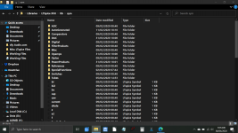
1/ The extracted folder marked Tube_sim contains a single folder called 'Tubes'. You stop at that point and right click and copy 'Tubes'. Don't open it any further to the individual files.
2/ Now navigate to Documents and locate the LTspice folder.
3/ Click the 'lib' folder to open it.
4/ Click the 'sym' folder to open it.
5/ Right click a blank spot and paste 'Tubes' into that 'sym' folder.
That is that one done.
It should look like this (attached images)
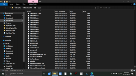
6/ Now click the extracted Tube_Lib folder and you should find a single file within.
7/ Right click that file and copy it.
8/ Navigate to Documents and LTspice again.
9/ Again navigate to 'lib' and open it.
10/ Click 'sub' to open it.
11/ Paste the .lib file into the folder. See attached image.
All done
Now (optional).
1/ Go to the original extracted .lib file in your Downloads folder and right click it and rename it to tube.txt
In other words you are changing the extension to .txt
You will get a warning that the file will become unusable but it doesn't matter because you have already pasted the correct version into place.
Now if you click the renamed .txt file you will see all it contains.
In fact I'll attach the .txt file here and then you can see it anyway.
Attachments
Nope. I followed your instructions to the letter, and no luck. Your screen-grabs are exactly what I was seeing. I'll head back to Windows 10 and try it again there. At least, I saw the magic word "Tubes" in the component selector, and successfully added one to the schematic. So now that I have the definitive set of instructions, I'll get it right by hook or by crook.OK, so then...
OK, it's working now in Windows 10. So, I have a problem with my Windows 7. 10 is behaving at the moment, so I'll plough on. Thanks for all that.Nope.

Right, that's important. I was going in through Programme Files. Many thanks.The path to add your models for ltspice in windows 7 is:
C:\Users\username\Documents\LTspiceXVII\lib
where "username" is the account name you use to logon to the computer.
- Home
- Design & Build
- Software Tools
- Installing and using LTspice IV (now including LTXVII), From beginner to advanced