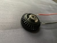
Have anyone tried putting a bass shaker on a panel?
like this one:
Buying a Dayton Audio BST-1 Bass Shaker? | SoundImports - SoundImports
or
Buying a Monacor BR-50 Bass Shaker? | SoundImports - SoundImports
or
Buying a Visaton BS130-4 Bass Shaker? | SoundImports - SoundImports
Theres also this thing which looks a bit like something inbetween:
Buying a Dayton Audio HDN-8 exciter? | SoundImports - SoundImports
as someone who has had to accommodate drummers using "throne thumpers" i've often wondered if they could be successfully used as "panel" driver motors.
Throne Thumper
could a two way DML be created?
(oops someone with the same thought was faster)
Throne Thumper
could a two way DML be created?
(oops someone with the same thought was faster)
i've sat on a drum throne with the Pearl unit i think it would eat the ones in kaptajnThomsen's list!
Thanks. That chapter and book is a good source of information. And that equation gives me an idea of which direction to head.
Your welcome, hope it helps.
My own suspicion is that the 2.5 * fo rule isn't the only factor. Just one of them, that determine how low you can get good DML performance.
Have anyone tried putting a bass shaker on a panel?
like this one:
Buying a Dayton Audio BST-1 Bass Shaker? | SoundImports - SoundImports
or
Buying a Monacor BR-50 Bass Shaker? | SoundImports - SoundImports
or
Buying a Visaton BS130-4 Bass Shaker? | SoundImports - SoundImports
Theres also this thing which looks a bit like something inbetween:
Buying a Dayton Audio HDN-8 exciter? | SoundImports - SoundImports
The HDN 8 isn't a good exciter ,I wasted £50 on a pair of these.
Steve
Hot Rodding Exciter on DML panel
There is the old adage “ No speaker sounds better than one you made yourself”
In that light, others should try this and see if my impressions are true.
I stuck a 3/4 inch diameter N52 ring magnet on the back of my DAEx32ep-4 vibrators on my DML panels. My thought was to increase flux density of the driver without adding significant weight(or a second panel vibrator) I would thereby be hot rodding or souping up my DML vibrators.
I think I am hearing more mid and high end detail in familiar recordings... maybe my imagination...
I’d love it if someone else could try it and post their opinion
Hmmm
I want to draw your attention to Figure 48a in the patent.
FIGS. 48 a and 48 b show a loudspeaker comprising a diaphragm in the form of a rectangular panel 280 and two transducers 282 mounted thereto. The panel is made from skinned, cored lightweight composite material. Two pairs of masses 288, 286 are mounted at locations at 19% and 88% of the distance from the centre to one corner of the panel (i.e. over the half-diagonal of the panel). The voice coil of each transducer 282 is mounted at a location which is 55% away from the centre of the panel along the half-diagonal. The panel is mounted to a chassis 281 by a suspension 283 and sealed in a baffle (not shown).
The locations of the transducers and masses are calculated in a similar manner to the earlier embodiments. The mode shapes for the X-axis and Y-axis are considered separately and may be computed from the bending stiffness and the surface area mass of the panel. The average nodal positions are calculated from the minima in impedance. In the embodiment shown, the locations of the masses and transducers are average nodal positions for both axes when the first three modes for each are considered. There are additional effective locations along the diagonal if four modes are addressed. For a panel of 460 mm by 390 mm, the (x,y) locations of each of the masses and transducers are given as follows:
First (x, y) Second (x, y) Component location location 1.38 g masses 186 mm, 158 mm) (274 mm, 232 mm) 6.4 g masses (28 mm, 23 mm) (432 mm, 367 mm) Transducers (104 mm, 88 mm) (356 mm, 302 mm)
The voice coils each have a mass of 4 g and the value of the masses is scaled to that of the voice coil as follows:
Half-diagonal relative Relative actual mass ratios ratios mass (gm) 0.88 1.35 1.35 6.40 0.55 1.00 1.00 4.00 0.19 0.35 0.35 1.38
The coil masses are not summed when obtaining the values for the balancing masses because each transducer relates only to the axis which it drives.
Attachments

Your welcome, hope it helps.
My own suspicion is that the 2.5 * fo rule isn't the only factor. Just one of them, that determine how low you can get good DML performance.
This is the other piece of the puzzle from the DML chapter.
4.9 Drive points
For an infinite panel, the location of the drive point is meaningless, but not so for a finite panel. To give optimal results, the drive should be at a point that couples to all the panel modes, and while ensuring de-correlation between panel velocity and drive point.
There are a number of locations on the panel that achieve this objective, and these can be determined by a number of methods. FEA is one such approach, and the eigenvalues for a free panel can be determined, along with the related mode shapes. These mode shapes are converted in contours of nodal lines, where the displacements are a minimum. Regions of no nodal lines represent potential positions to drive the panel. It is usually only necessary to look at the first 20 or so sets of modes in the nodal map in order to find suitable candidates as drive points. These drive points are already known for complete sets of panel sizes and aspect ratios, but for optimal performance the ratios of panel length to width, as well as the most appropriate target values for B and are already known, as an integral part of the invention.
By way of example, an FEA model was constructed for a typical DML panel, and the model solved. By extracting the panel displacements associated with each mode, it is possible to generate composite maps for 20 modes (Fig. 4.9) and 30 modes (Fig. 4.10). Care should be taken with higher mode orders because of the accuracy of the FEA solvers at higher eigenfrequencies.
Attachments
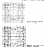
The patent KoAP posted shows how they used weight and exciter locations with regard to the node map.
Node Map
Wouldn’t the node map indicate that the exciter should be placed roughly in the center of the panel but not on the node line? That would place the exciter near the (1,1) mode but not on it? It seems most of us hobby types have been placing our exciters at a position using the so called 2/5, 3/5 measurements which places the exciter on top of the area of highest node line density(least movement). The 2/5, 3/5 placement seems counter to idea of placing vibrator at max vibrational area if nodes are where little move to occurs in the node map (chladni pattern) of a panel.
Wouldn’t the node map indicate that the exciter should be placed roughly in the center of the panel but not on the node line? That would place the exciter near the (1,1) mode but not on it? It seems most of us hobby types have been placing our exciters at a position using the so called 2/5, 3/5 measurements which places the exciter on top of the area of highest node line density(least movement). The 2/5, 3/5 placement seems counter to idea of placing vibrator at max vibrational area if nodes are where little move to occurs in the node map (chladni pattern) of a panel.
Last edited:
Wouldn’t the node map indicate that the exciter should be placed roughly in the center of the panel but not on the node line? That would place the exciter near the (1,1) mode but not on it? It seems most of us hobby types have been placing our exciters at a position using the so called 2/5, 3/5 measurements which places the exciter on top of the area of highest node line density(least movement). The 2/5, 3/5 placement seems counter to idea of placing vibrator at max vibrational area if nodes are where little move to occurs in the node map (chladni pattern) of a panel.
They don't place the exciter in the center because...
"To give optimal results, the drive should be at a point that couples to all the panel modes, and while ensuring de-correlation between panel velocity and drive point."
Decorrelating (decoupling) the initial impulse from the modes improves the soundfield.
The advantage of DML is a wide *diffuse* soundfield. You would probably get the wide soundfield if you placed the exciter in the center but you'd harm the diffuse soundfield.
A diffuse soundfield is an advantage because it tames undesirable room reflections. The result is better intelligibility, better imaging (stereo), and a wider sweet spot.
Last edited:
I do not understand. We hit marimbas in the center, we hit drums in the center, the bridge of most musical instruments are I the “center” of an acoustic radiator. All of these have in common excitation of f0 or the fundamental of the instrument by exciting them at the antinode of the fundamental as well as exciting multiple overtones.
Why would, in the case of a DML, vibrating the location of most of the nodes produce a wide sound field. Stimulating the nodes of modes in musical instrument produces dull sound. Think hitting drum rim, or a guitar edge.
I am missing something conceptual.
Why would, in the case of a DML, vibrating the location of most of the nodes produce a wide sound field. Stimulating the nodes of modes in musical instrument produces dull sound. Think hitting drum rim, or a guitar edge.
I am missing something conceptual.
Last edited:
I need to do more reading on this topic. I do appreciate your answer I still fail to understand why exciting the nodes ( decoupling) in a DML produces a wide sound field with minimal room issues but in instruments stimulating only nodes produces dull thuds and stimulating antinodes fills a room with pleasing sound(eg violin)
For now, in the case of the DML, I can simply accept that it does[emoji4].
Thank you for your answer and your multiple thoughtful contributions to this thread. Brain food for sure!
For now, in the case of the DML, I can simply accept that it does[emoji4].
Thank you for your answer and your multiple thoughtful contributions to this thread. Brain food for sure!
With full range DML panels most people boost the bass which in turn will make the frequency response uneven and cause other sorts of problems.
A DML sub wont slam like a conventional cone driver or play as low mostly because exciters are limited and made for full range duty. I wish they would make specific exciters that could be used for sub duty by making them more powerful and able to handle at least 100 watts rms.
. A DML sub also sounds more articulate and life like then a conventional cone boxed sub in which they appear to disappear just like with most Open baffle subs/speakers.
For low-frequency panels in my opinion, it is better to use an inertial vibration transducer whose idea is shown here:https://patentimages.storage.googleapis.com/17/d6/68/056c7b44d24efe/CA2229858C.pdf and the implementation here:the goldy - AER Loudspeakers
They don't place the exciter in the center because...
Decorrelating (decoupling) the initial impulse from the modes improves the soundfield.
The advantage of DML is a wide *diffuse* soundfield. You would probably get the wide soundfield if you placed the exciter in the center but you'd harm the diffuse soundfield.
A diffuse soundfield is an advantage because it tames undesirable room reflections. The result is better intelligibility, better imaging (stereo), and a wider sweet spot.
Hi Bradley pnw
You are drawing too many conclusions from the patents, putting the exciter in the centre of the panel is the worst place because you would be setting off strong standing waves ,as Davidlang points out the centre would act like a drum ,you don't want your panel to have resonance preferences it is not a musical instrument.
Shelly katz of podium fame is now saying that you should have both direct radiated sound ,he uses standard cone speakers,and dml ,the best of both worlds you could say.
I to believe this to be true, but use different methods to achieve the same outcome.
Steve
Hi Bradley pnw
You are drawing too many conclusions from the patents,
Veleric directed me to a book titled Loudspeaker and Headphone Handbook, by Graham Banks. Chapter 4 covers DMLs. KoAP's patent reference showed a practical application of the content discussed in that chapter.
Standing waves would probably be more of an equalization problem. I assume that's why KoAP's patent reference had weights attached to the panel. However, exciting the nodes so you de-correlate the drive point from the modal radiation appears to be the primary benefit of a DML. That's what supplies the diffuse soundfield that does so many great things.
At present, I'm thinking exciter location optimizes modal radiation and a physical modification like a weight equalizes/tames standing waves.
Loudspeaker and Headphone Handbook, Third Edition - PDF Free Download
Last edited:
Shelly katz of podium fame is now saying that you should have both direct radiated sound ,he uses standard cone speakers,and dml ,the best of both worlds you could say.
I to believe this to be true, but use different methods to achieve the same outcome.
Steve
Why does Katz say that, what's his reasoning?
For example, I think you should have a diffuse soundfield above Schroeder because you're dealing with ray acoustics in a small room. Below Schroeder I think you should have separate low frequency sources so you can implement a small room mode equalization strategy (Harman/Welti, Geddes, near field, ?) I'd argue traditional subs would be a good low frequency source because they are so well understood and easy to build. On the other hand, low frequency panels might be great too.
- Home
- Loudspeakers
- Full Range
- A Study of DMLs as a Full Range Speaker