Thank you all for the answers.
I want to clarify that I never doubted the accuracy of the PCB. The purpose of my questions was only to clarify me (as far as I can understand) some ideas to understand how a circuit works, however simple it may be, and not just mount it, as if it were a model kit. I never said that the PCB is wrong but if my reasoning was wrong, and indeed it was.
In truth I had written privately to 6L6, but he rightly invited me to write in the forum so that it could be interesting for others.
Since it is really easy to invert the wires of AC line, then can I use two 1.25A fuses in my module?With 220V mains 1.25A. HOWEVER, your country may not allow a fuse on the neutral. You may be able to bypass that depending on the IEC inlet connections. Make sure to follow local AC mains wiring rules and regulations.
Last edited:
Alternate Brand of Transformer
I have all the parts for a "DIY-Store Ver 3.0" power supply board. I am using 22000uF 35 volt capacitors. I am going to power an F5 Version 3 power amp from the DIY store. I want to use an "Antek" AS-3218 or an AS-4218. These two transformers have been out of stock for quite sometime. I called customer service and was informed that a shipment would arrive in 2 or 3 weeks.😕 Is there another brand that is available? The "Plitron" web site is busted. Has anyone used a "Torid" https://toroid.com transformer with the same specifications as the two anteks mentioned. If someone has, could you suggest a model number.
I assembled an "ACA 1.6" I bought myself for Christmas. I had forgotten how good 2 channel music sounds. I had a "Big Ole Stereo" while I was in college. Somehow it got lost in the last 40 years. Thank God and Nelson Pass I kept all "487" of my Vinyl Albums. I don't know who invented "MP3" codec but I am going to punch them in the mouth when I get home.
Anyway back to the topic, I need more power. I think the F5 will fit the bill nicely.
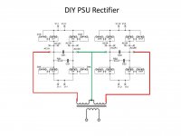
I want to use the rectifier stage of the DIY Universal PSU with a center-tapped transformer, and I want to snubber both legs against CT prior to rectification as shown in the attachment below. I'm pretty sure that the design of this board doesn't allow this--am I correct?Can someone confirm or deny my suspicion?
Thanks,
Ron
Thanks,
Ron
Attachments

Rinman77, I have good news: you are mistaken. Please post an image of the Universal Power Supply circuit schematic diagram; then we can point out the components on that board, which implement the transformer secondary snubbers.
Please is it possible that someone will answer me to my question at post #1202?
I remind you that my module have two fuses and does'nt have the ability to bypass one of these.
Thank you
I remind you that my module have two fuses and does'nt have the ability to bypass one of these.
Thank you
Thank you all for the answers.
I want to clarify that I never doubted the accuracy of the PCB. The purpose of my questions was only to clarify me (as far as I can understand) some ideas to understand how a circuit works, however simple it may be, and not just mount it, as if it were a model kit. I never said that the PCB is wrong but if my reasoning was wrong, and indeed it was.
In truth I had written privately to 6L6, but he rightly invited me to write in the forum so that it could be interesting for others.
Since it is really easy to invert the wires of AC line, then can I use two 1.25A fuses in my module?
if you have IEC with separate fuses for each side , use both fuses , logically
value of each same as when calculating for case of just one
in fact , that's best option - having both rails fused , when living in country where plugs are not phase-oriented ( you can rotate it) , as is in my country , and number of them in Eu
I want to use the rectifier section of the PCB for two +60 vdc rails using the MUR3020 diodes. I separated the rectifier section from the capacitor section.
Do I populate the rectifier board with all four diodes on each section?
Or do I populate the rectifier board with half the diodes on each section and only use the V+ on each board?
Do I populate the rectifier board with all four diodes on each section?
Or do I populate the rectifier board with half the diodes on each section and only use the V+ on each board?
What transformer?
EDIT: Ok, now I'm visualizing what you are asking.
Stuff both diode sections with 4 diodes each.
DO NOT CONNECT GND together on the PSU.
On the D1 side, the connections will be labeled properly. But on the D2 side, the "GND" position will be positive and "V-" will be ground.
EDIT: Ok, now I'm visualizing what you are asking.
Stuff both diode sections with 4 diodes each.
DO NOT CONNECT GND together on the PSU.
On the D1 side, the connections will be labeled properly. But on the D2 side, the "GND" position will be positive and "V-" will be ground.
Last edited:
I want to use the rectifier stage of the DIY Universal PSU with a center-tapped transformer ...
Is it a "true" center tapped transformer, with only three secondary wires?
Or is it a dual secondary transformer, with four secondary wires, but two of the wires are connected together to establish a middle connection?
Mark,Is it a "true" center tapped transformer, with only three secondary wires?
Or is it a dual secondary transformer, with four secondary wires, but two of the wires are connected together to establish a middle connection?
See below. It is a "true" CT transformer--only 1 wire defines CT. If one is "allowed" to share the CT to both sides of the circuit, I would try to connect as shown below. But I didn't know you could do that. I'm happy to be wrong about that.
I should also mention that my application is a +/- dual rail supply for a class AB amplifier. I'm modifying an existing supply, not starting from scratch, so I don't have the luxury of choosing my transformer characteristics.
Thanks,
Ron
Attachments

Mark,
See below. It is a "true" CT transformer--only 1 wire defines CT. If one is "allowed" to share the CT to both sides of the circuit, I would try to connect as shown below. But I didn't know you could do that. I'm happy to be wrong about that.
I should also mention that my application is a +/- dual rail supply for a class AB amplifier. I'm modifying an existing supply, not starting from scratch, so I don't have the luxury of choosing my transformer characteristics.
Thanks,
Ron
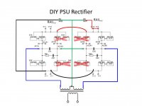
Or here's an alternate proposal, which uses fewer diodes, and seems not to break any rules. But maybe I'm making things way too complicated...
Attachments
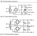
If you use a center tapped transformer (Figure 19.1), the center tap goes directly to ground. And there are only four diodes in the power supply.
If you use a transformer with dual independent secondaries (Figure 19.2), each of the two bridge rectifiers {eight diodes in the power supply} has an output connected to ground.
I am beginning to think you won't be able to use the diode board with your transformer; I am beginning to think you will have to create your own diode board. You can use the filter capacitor board with C-R-C. But not the diode board. The diyAudio Universal Power Supply PCB was designed with dual independent secondaries in mind.
_
Attachments
🙄Ha ha, yeah, that's what I already have--less complicated for sure!
Thanks Mark, I've been staring at those same two diagrams from Bob's book.If you use a center tapped transformer (Figure 19.1), the center tap goes directly to ground. And there are only four diodes in the power supply.
If you use a transformer with dual independent secondaries (Figure 19.2), each of the two bridge rectifiers {eight diodes in the power supply} has an output connected to ground.
I am beginning to think you won't be able to use the diode board with your transformer; I am beginning to think you will have to create your own diode board. You can use the filter capacitor board with C-R-C. But not the diode board. The diyAudio Universal Power Supply PCB was designed with dual independent secondaries in mind.
_
Did you look at my alternate proposal? It seems to like it could work with the use of a couple jumpers on the board.
Thanks Mark, I've been staring at those same two diagrams from Bob's book.
Did you look at my alternate proposal? It seems to like it could work with the use of a couple jumpers on the board.
But a very compact rectifier board which allows for custom snubbering + choice of diodes would be very nice. Perhaps one with surface mount components so that it cold be fit nicely in place of the standard bridge. I'm surprised one doesn't already exist.
The bodge / kludge / rig-of-the-merde shown in #1212 looks like it may work electrically, I have no idea if the required modifications are easy or difficult.
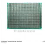
I, personally, would feel more comfortable assembling my own custom board that I wired myself and checked myself. On a little scrap of prototyping board (link) like the stuff shown in the photo below
_
I, personally, would feel more comfortable assembling my own custom board that I wired myself and checked myself. On a little scrap of prototyping board (link) like the stuff shown in the photo below
_
Attachments
The bodge / kludge / rig-of-the-merde shown in #1212 looks like it may work electrically, I have no idea if the required modifications are easy or difficult.
I prefer to call it the MacGyver version😎.
("rig-of-the-merde"...I work for a French company
 )
)I did that already, but it weren't so prettyI, personally, would feel more comfortable assembling my own custom board that I wired myself and checked myself. On a little scrap of prototyping board (link) like the stuff shown in the photo below
_
 .
.Hi all
Re: post #1083 on page 109 and the Universal Power Supply for 240V use
The AC Line capacitor is listed as 33pF with the following Mouser part number 667-ECQ-U2A332ML.
ECQ-U2A332ML Panasonic | Mouser New Zealand
It appears I have incorrectly ordered and for some reason have ordered a 33pF Mica Capacitor with the Mouser par number 598-CD15ED330JO3F.
CD15ED330JO3F Cornell Dubilier - CDE | Mouser New Zealand
No clue as to how I got that one in my shopping basket lol Is this one useable and if not what are the repercussions of not using a capacitor in this position?
Thanks
Hi all
Re: post #1083 on page 109 and the Universal Power Supply for 240V use
The AC Line capacitor is listed as 33pF with the following Mouser part number 667-ECQ-U2A332ML.
ECQ-U2A332ML Panasonic | Mouser New Zealand
It appears I have incorrectly ordered and for some reason have ordered a 33pF Mica Capacitor with the Mouser par number 598-CD15ED330JO3F.
CD15ED330JO3F Cornell Dubilier - CDE | Mouser New Zealand
No clue as to how I got that one in my shopping basket lol Is this one useable and if not what are the repercussions of not using a capacitor in this position?
Thanks
Do not omit, do not use what you ordered, it needs to be X1/Y2 rated for AC.
- Home
- Amplifiers
- Power Supplies
- diyAudio Power Supply Circuit Board v3 illustrated build guide