If you are interested in any more of my ideas...
It depends on the amount of work required to implement them 🙂.
In the future if you included within the options, smaller increments that would be awesome.
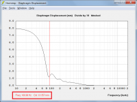
I assume you are referring to the loudspeaker wizard charts. It would complicate things greatly to start changing ranges and increment values beyond those that are already provided. If you need to know exact diaphragm displacement values, go back to the main chart and sample at the desired frequency. The result will be accurate to four decimal places.
Thank you for using my idea for the spectrogram.
You're welcome. You are just lucky that it was easy to do... 🙂.
Attachments
Hi David McBean,
thank you for Hornresp !
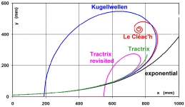
I am interested in JMMLC 'tractrix revisited' and therefore I would beg you to add this curve.
The radius for the Tractrix curve is 1/2 of the Spherical, the 'tractrix revisited' is just a Spherical using 1/2 of the normal radius.
I think you could do it by using L23 as input field for the factor of the radius (for L12=Sph). If L12 =Sph and L23=1 then you get the Spherical, if L12=Sph and L23=0.5 you get the 'tractrix revisited' and for other values of L23 you would get 'your own' custom curve.
The usable cutoff frequency for Tractrix horns seems to be 1.5 to 2 times higher than caculated. The 'revisited' will be shorter than the standard Tractrix, therefore the real cutoff is probably 2 times the calculated.
Thank you very much.
thank you for Hornresp !
I am interested in JMMLC 'tractrix revisited' and therefore I would beg you to add this curve.
The radius for the Tractrix curve is 1/2 of the Spherical, the 'tractrix revisited' is just a Spherical using 1/2 of the normal radius.
I think you could do it by using L23 as input field for the factor of the radius (for L12=Sph). If L12 =Sph and L23=1 then you get the Spherical, if L12=Sph and L23=0.5 you get the 'tractrix revisited' and for other values of L23 you would get 'your own' custom curve.
The usable cutoff frequency for Tractrix horns seems to be 1.5 to 2 times higher than caculated. The 'revisited' will be shorter than the standard Tractrix, therefore the real cutoff is probably 2 times the calculated.
Thank you very much.
the 'tractrix revisited' is just a Spherical using 1/2 of the normal radius.
Are you sure?
My understanding is that it is more complicated than that.
the 'tractrix revisited' is just a Spherical using 1/2 of the normal radius.
Just to clarify - by "normal radius" do you mean the fixed radius of the spherical wavefront, or the varying radius of the circular cross-sectional area normal to the horn axis?
My understanding is that it is more complicated than that.
I initially thought the requested profile was the one given at:
A True Expansion Tractrix Horn – Sphericalhorns
I subsequently came across the following thread which clarified what profile was actually being asked for:
https://www.diyaudio.com/forums/multi-way/351208-calculate-tractrix-revistid.html#post6122803
I will investigate the possibility of including the second profile in Hornresp (the purple trace in the attachment). It should require a lot less work to implement than the one I originally assumed was being requested. The maximum mouth flare tangent angle will however be limited to 90 degrees - the horn profile will not fold back as shown in the diagram.
Attachments
I initially thought the requested profile was the one given at:
A True Expansion Tractrix Horn – Sphericalhorns
I subsequently came across the following thread which clarified what profile was actually being asked for:
https://www.diyaudio.com/forums/multi-way/351208-calculate-tractrix-revistid.html#post6122803
I will investigate the possibility of including the second profile in Hornresp (the purple trace in the attachment). It should require a lot less work to implement than the one I originally assumed was being requested. The maximum mouth flare tangent angle will however be limited to 90 degrees - the horn profile will not fold back as shown in the diagram.
Sorry for the late reply. Yes, I think it should be very easy for you, you just need to add the input field (L23 ?) for the factor "a" to the spherical curve.
You have already the constant radius of the spherical r0 = c / (pi * Fc) and you just add r0 = r0 * a in your code.
L23 = a = 1 will give you the "spherical"
L23 = a = 0.5 for "tractrix revisited" and
L23 = a = whatever reasonable number you like for "user special curve"
Off topic: most front loaded horns are created by rotating their curve around their axis. Using these horns for low frequencies (80Hz or so) their circular mouth is close to the floor.
Would it be worthwhile to make the mouth a semicircle to be closer to real 2pi condition ?
Usually the mouth of the horn is 90 degree to the floor, would it be worthwhile to use more of the floor by gradually making the horn longer from top to bottom (imagine a conical horn cut by an inclined plane) ?
This update has required extensive modifications to the program, and it is possible that something has been missed / overlooked during testing. Could you please report any bugs.
I am happy to oblige. This is the first "bug" report so far I believe.
CHANGE 2
A loudspeaker with an offset driver can now also have an offset port, an offset passive radiator or an offset stub.
I have made a Hornresp version of the Akabak script I made a couple of weeks ago. The small differences are not big enough for a bug report, but they will intrigue some of the experts here.
https://www.diyaudio.com/forums/subwoofers/350497-akabak-simulation-br.html#post6130357
But when I try to export to Akabak I get a popup! A closed duct in Akabak is done by wiring to 0.
Code:
Duct 'Above port'
    Node=10=0
PS. Thanks David for implementing this! DS.
The small differences are not big enough for a bug report, but they will intrigue some of the experts here.
Hi Mårten,
Thanks for the feedback. There are three reasons for the differences you are seeing.
* Path length is 48 cm in Hornresp and 0 cm in AkAbak
* Eg is 40 volts in Hornresp and 0.707 volts in AkAbak
* Hornresp is showing the power response and AkAbak is showing the pressure response
I tested the new Hornresp offset models extensively prior to releasing the update. The testing included a series of sanity checks against other models that I knew were working correctly. (By reducing the offsets to very small values it was possible to do all sorts of comparisons against the other models). I checked to confirm that all the compared results were effectively identical.
I would be very surprised indeed, if there is anything wrong with the new simulation models 🙂. My main concern was that there might be bugs in the operation of the user interface, but so far, so good, it seems...
Kind regards,
David
But when I try to export to Akabak I get a popup!
No new loudspeaker AkAbak export options have been added to Hornresp for quite some time now. It is just too much work to include them.
Hi alujoe2,
It will still require a fair amount of work to implement the necessary changes in a seamless fashion across all parts of the program. The factor will be designated "T" (similar to the hyperbolic-exponential horn flare parameter T) and will be limited to the range 0.50 to 1.00.
T = 1.00 will be "Spherical wave"
T = 0.50 will be "Exponential tractrix"
0.50 < T < 1.00 will be "Custom profile"
In theory, the more tightly the mouth couples to the half space environment the better, but in a closed room I am not sure how much practical improvement would be gained by adopting the measures suggested. They should not make things any worse though... 🙂.
Kind regards,
David
I think it should be very easy for you
It will still require a fair amount of work to implement the necessary changes in a seamless fashion across all parts of the program. The factor will be designated "T" (similar to the hyperbolic-exponential horn flare parameter T) and will be limited to the range 0.50 to 1.00.
T = 1.00 will be "Spherical wave"
T = 0.50 will be "Exponential tractrix"
0.50 < T < 1.00 will be "Custom profile"
Would it be worthwhile to make the mouth a semicircle to be closer to real 2pi condition ? Usually the mouth of the horn is 90 degree to the floor, would it be worthwhile to use more of the floor by gradually making the horn longer from top to bottom (imagine a conical horn cut by an inclined plane) ?
In theory, the more tightly the mouth couples to the half space environment the better, but in a closed room I am not sure how much practical improvement would be gained by adopting the measures suggested. They should not make things any worse though... 🙂.
Kind regards,
David
It will still require a fair amount of work to implement the necessary changes in a seamless fashion across all parts of the program.
Hi David, thank you very much for doing all the work !
I know changes to a program are a lot of work. English is not my native tongue, sorry if I did say something wrong ! I wanted to say you are a clever person and therefore it should be easy for you, I did not want to say this is done in 5 minutes.
The factor will be designated "T" (similar to the hyperbolic-exponential horn flare parameter T) and will be limited to the range 0.50 to 1.00.
T = 1.00 will be "Spherical wave"
T = 0.50 will be "Exponential tractrix"
0.50 < T < 1.00 will be "Custom profile"
Is there a special reason to limit T to 0.5 or can you please make
0.40 <= T < 1.00 for "Custom profile" ?
Another question: how can I change the default driver ? If I use F7 I always get the default driver, no matter which driver I haven choosen before. I tried changing the values in /Drivers/Default Driver.txt, but that doesn't help.
Hi Mårten,
* Path length is 48 cm in Hornresp and 0 cm in AkAbak
With Path length 0 in Hornresp I get the same rsponse as in Akabak.
Thanks David!
Maybe you should add an orientation variable? Hornresp is tailored for horizontal horns, but this simulation is a vertical BR.
Hi Everyone,
CHANGE 2
A loudspeaker with an offset driver can now also have an offset port, an offset passive radiator or an offset stub.
It can be used to simulate closed boxes as well. I have simulated 4 different dogbox designs here: Simulating 18sound 10nmba520 dogbox
Hi alujoe2,
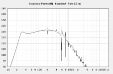
For a given S1, S2 and L12, changing T from 0.5 to 0.4 makes no practical difference to the results. To illustrate, the attachment compares the power responses for the two cases. If you look very closely at the first ripple peak it is just possible to see the grey trace (T = 0.4) fractionally above the black trace (T = 0.5).
You cannot.
You need to copy / paste drivers from one record to another, or copy / paste from the driver database. The necessary commands are under the main input window File menu.
Kind regards,
David
Is there a special reason to limit T to 0.5 or can you please make 0.40 <= T < 1.00 for "Custom profile" ?
For a given S1, S2 and L12, changing T from 0.5 to 0.4 makes no practical difference to the results. To illustrate, the attachment compares the power responses for the two cases. If you look very closely at the first ripple peak it is just possible to see the grey trace (T = 0.4) fractionally above the black trace (T = 0.5).
how can I change the default driver ?
You cannot.
You need to copy / paste drivers from one record to another, or copy / paste from the driver database. The necessary commands are under the main input window File menu.
Kind regards,
David
Attachments

Maybe you should add an orientation variable?
It's not going to happen 🙂.
For a given S1, S2 and L12, changing T from 0.5 to 0.4 makes no practical difference to the results. To illustrate, the attachment compares the power responses for the two cases. If you look very closely at the first ripple peak it is just possible to see the grey trace (T = 0.4) fractionally above the black trace (T = 0.5).
Hi David,
I agree with you, but isn't there a big difference in size between T = 0.4 or T = 0.5 if you build it with the back folded part ? I would build the horn in "gramaphone style" with facets that fold back (similar to Le Cléac'h horns as they are usually built), therefore I was asking for T = 0.4
It can be used to simulate closed boxes as well. I have simulated 4 different dogbox designs here: Simulating 18sound 10nmba520 dogbox
I need some help with reasonable values for Fr1 in Loudspaker Wizard. The response starts to look ok with Fr1=250.
It can be used to simulate closed boxes as well. I have simulated 4 different dogbox designs here: Simulating 18sound 10nmba520 dogbox
Take a look at these simulations David. I had expected a rise in response at a quarter wavelength for the cylindrical dogbox. But there is only a resonance at half a wavelength depth.
- Home
- Loudspeakers
- Subwoofers
- Hornresp