Just saw your post Doug - my jumpers are on default (as it came) which I believe is the SE setting as far as I can tell visually so have left them alone.
In both cases on the left two pins, per the photo.
I'm very happy you got it working. I'll look forward to the photos.
(just got to wait for my STDP switch)
That's SPDT ... Single Pole, Double Throw.
Hi all. I had a problem testing my system - All went well with the set up but just as I was about to pack it up and clear my table before my other half came home it stopped working. Fault light and clipping light came on! I tried connecting reset to ground then fault pin to ground but to no avail. Don't know what I did, the only thing I was playing music (quietly) bot only one speaker connected ( I did read somewhere you should have a load on the amp when on) so don't know if that has anything to do with it? I turned it off at the mains for 10 minutes but just came back on with the faults lights on. How do I reset it or have I somehow screwed it? Help?
Hi all. I had a problem testing my system - All went well with the set up but just as I was about to pack it up and clear my table before my other half came home it stopped working. Fault light and clipping light came on! I tried connecting reset to ground then fault pin to ground but to no avail. Don't know what I did, the only thing I was playing music (quietly) bot only one speaker connected ( I did read somewhere you should have a load on the amp when on) so don't know if that has anything to do with it? I turned it off at the mains for 10 minutes but just came back on with the faults lights on. How do I reset it or have I somehow screwed it? Help?
The fault indicator is an output. Shorting it to ground is a bad idea.
Before you do anything else, get a pen and some paper and draw a schematic of exactly what you have hooked up to it. If you need further help, post it here...
Disconnect everything you've done from the module ... power it down then back on with two speakers connected and no inputs... does the fault indicator still light up?
There are a list of things that will cause the fault condition in the TPA3251 Spec Sheet beginning on page 17.
For the record previous to this I had the rest pin and ground pin hooked up to the switch (DPDT) which all worked well so was very pleased thanks for that idea Doug). I disconnected that side of it and was making a cuppa when it went quiet and fault came on. Anyway, Looking at spec sheet think it may be some sort of over heating, anyway will try tomorrow and see what happens.
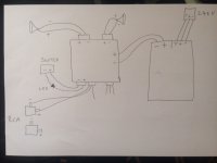
Diagram of wiring at the time - can't wire it back up again until tomorrow but will try as you say and see what happens. (My fault to ground was only for a moment so hopefully didn't do harm)
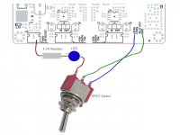
From the drawing and explanation I don't think you have that standby switch sorted. See the thumbnail. It should be exactly that simple.
There are a number of conditions in which Fault will latch on. This includes all nature of speaker protection, supply protection and heat protection. When it latches it won't release until the power is removed... BUT ... with the big caps on that board it could take them several minutes to drain, so off and back on isn't going to get it... it might be more like off, go have supper, back on.
If you have a voltmeter, take readings of your power supply, speaker offset, and the voltage on the reset circuit and make sure they are correct before proceeding. (If you don't have a voltmeter, get one.)
Finally... Just to cover the my bases ... you should be using plugs that fit your board with the wiring connected to them... especially on the power and speaker connections.
Attachments
Last edited:
Hi Doug, thanks for getting back to me - I think my diagram caused a little confusion. I did have it all wired up correctly as per your original thumbnail and it worked perfectly. It was only after that I realised my old toggle switch had a bad connection on on e side ( it is a Double throw as that is what I had) and to be sure I just connected the 12v led side without the reset pin so the amp continued to play music quietly while I used the switch to turn on/off the LED to confirm the switch had a bad connection on one side. After that with the amp on and the switch in the on/led on position I started to make a cuppa when the amp died (hope that is not to confusing.
Anyway, hooked it up again today as you said without inputs connected and it just came straight on with the fault/clip lights on (Boo!). measured input which showed 51v which seemed high as PS was not turned up full (it showed 46v when I first hooked it up) The reset pin was 3.09v. The speaker offset I'm not to sure about - I think it showed 0.0 on one side and 0.3mv on the other? Turned amp off and left it for 20 mins (which may not have been long enough) and turned PS down to 45v before turning it all on again with inputs connected - same fault/clip lights !!! Very disappointed given it had been working so well. Not sure what I can do?
Anyway, hooked it up again today as you said without inputs connected and it just came straight on with the fault/clip lights on (Boo!). measured input which showed 51v which seemed high as PS was not turned up full (it showed 46v when I first hooked it up) The reset pin was 3.09v. The speaker offset I'm not to sure about - I think it showed 0.0 on one side and 0.3mv on the other? Turned amp off and left it for 20 mins (which may not have been long enough) and turned PS down to 45v before turning it all on again with inputs connected - same fault/clip lights !!! Very disappointed given it had been working so well. Not sure what I can do?
Anyway, hooked it up again today as you said without inputs connected and it just came straight on with the fault/clip lights on (Boo!). measured input which showed 51v which seemed high as PS was not turned up full (it showed 46v when I first hooked it up) The reset pin was 3.09v. The speaker offset I'm not to sure about - I think it showed 0.0 on one side and 0.3mv on the other? Turned amp off and left it for 20 mins (which may not have been long enough) and turned PS down to 45v before turning it all on again with inputs connected - same fault/clip lights !!! Very disappointed given it had been working so well. Not sure what I can do?
The spec sheet has a list of the various states that will signal ot and fault lights, some latch some don't... you'll need to look there and see if there are any clues.
The problem at this moment is you are way over there and I am way over here ... makes it hard for me to troubleshoot for you.
What is the minimum voltage for that board? Try that...
Is the 12volt output showing 12 volts? The chip won't work without it.
Speaker offsets should be 0 all the time, but with the unit in fault, they are turned off, so you can't really measure them. Do check right away if you get it out of latched on fault condition.
Have you done any soldering on the board? If so you should check for bridges or cold/bad joints.
Try disconnecting the standby circuit entirely and power cycle it...
Is there any chance your speakers are shorted?
Is there any chance your inputs are shorted?
Does anyone else have any suggestions? 😱
Thanks Doug, don't mean to take up so much of your time. Will hook it all up again tomorrow and go through it. (the 12v was still reading 12v I forgot to mention that)
Thanks Doug, don't mean to take up so much of your time. Will hook it all up again tomorrow and go through it. (the 12v was still reading 12v I forgot to mention that)
No worries ... I seem to be staying home a lot these days, so have some free time on my hands. 🙂
Let me know how you make out.
.....and here I go again
Well I tried again today to no avail. Fault and clip light came on instantly - tried toggle on/off with reset but nothing changed. Left it off for a couple of hours before turning it on with the reset in standby - lights straight on again. Voltage was at lowest (42v) that I could lower it to.
Speakers not shorted (works on old amp)
Inouts from laptop fine (works on old amp)
Speaker outputs read 0.0
No soldering from me
Tried powering it up and down but lights on instantly each time.
Don't know what else is left to do?
The clip light (Clip-OTW)seems to be due to Thermal warning which confuses me even more as it comes on instantly. I can;t find how you use the fault/clip pins next to the reset pin? Does anyone (don't want to put it all on Doug) know what else I could do to reset the amp board? I'm generally good at working out DIY problems including household appliance electronic etc but with electronics like this I really don't which is really frustrating especially as it had been working perfectly before.
Attachments
Sadly, I have to agree with Jim. I just did the same thing to my TPA3116 4 chip board so I know it isn't what you would want to hear.
I considered transplanting a new chip to the board but I imagine it is not an easy task
However, it's not confirmed as yet 🙁
I considered transplanting a new chip to the board but I imagine it is not an easy task
However, it's not confirmed as yet 🙁
The clip light (Clip-OTW)seems to be due to Thermal warning which confuses me even more as it comes on instantly. I can;t find how you use the fault/clip pins next to the reset pin?
They appear to be outputs for external LEDs.
Does anyone (don't want to put it all on Doug) know what else I could do to reset the amp board? I'm generally good at working out DIY problems including household appliance electronic etc but with electronics like this I really don't which is really frustrating especially as it had been working perfectly before.
Oh heck, put it on me, everyone else does anyway... 🙄
I'm with the others on this one, I think you've somehow fried the chip on that board. Unfortunately a lot of DIY modules like this are cheaply made and poorly designed, so it's not unheard of for them to just give up and lay down to die.
The 8255 chip is different than the 3116 chip, even though they use the same basic Class D guts. The 8255 requires an external 12volt supply to drive it's input and protection stages... that's the same supply that is fed out to the connector at the edge of the board. Short that out and the whole thing does the funeral march. So... check the voltage on that connector... and see if it's still working. If not, you have your answer.
There is also the (unlikely) possibility that it doesn't like being held in Reset for long periods of time. But the spec sheets and board descriptions say nothing about that being an issue.
Last edited:
I think doing so blows an output inductor...but I may well be very wrong
It's more likely that back EMF from the output filters spikes the drivers inside the chip. Any idea how hard it is to burn out a coil??
I considered transplanting a new chip to the board but I imagine it is not an easy task
Now there's an understatement of some size 🙁
Unless you've done medium density surface mount soldering before, it is all but impossible to replace most of this stuff. You quite literally end up working through a microscope...
- Home
- Amplifiers
- Class D
- 3E audio board reset