In (some?) class D amplifiers, the gain follows the voltage of the output stage supply - so varying this would change the output. I think that Lyngdorf has made this.
//
//
I would be wary about moving the pot... a hot mic could overload the amp or create substantial distortion with no way of backing up the gain.
A 1 kOhm resistor will add a grand total of 4 nV/√(Hz) of voltage noise, entirely negligible vs. tube input noise.
I looked up the old IRT V 76 module, and they say 1:30 on the input and 9:1 on the output - these could be impedance ratios though, which would amount to 1:5.5 input and 3:1 output turns-wise.
Mind you, you could also "cheat" and add a solid-state "pre-preamp" stage right after the input transformer (or even instead of it - do you have phantom power?). Something JFET cascoded with a small high-voltage MOSFET? It doesn't even have to be a super low noise JFET, just something small that's decent at maybe 500 µA to 1 mA. Consulting Horowitz/Hill and Mouser, I'm finding precious little overlap, maybe SMP5484 would be something (not sure about their 1/f noise properties though, and they should how 2N5486 may vary widely). There would also be the 2SK208-Y and 2SK879-GR, SMD versions of the trusty 2SK30 JFET found in various audio gear. Now if those aren't suitable I don't know what is.
If that JFET business seems like too much fuss, you could get a KSC3503DS or similar BJT - Vceo = 300 V, Cob = 2.6 pF and fT=150 MHz sounds suitable to me. (Beta seems stable down to at least 100 µA, but GBW suggests that you better run 1 mA, which should yield a little over 30 MHz.) Then you'd have to come up with a base bias supply though. On the plus side, you could probably use 470 ohms of emitter degeneration and a 200-300 ohm base stopper with minimal impact on noise. Even then, gain may still be so high that splitting the load resistor (and maybe bridging part of it with a capacitor) or implementing some voltage feedback could become necessary. I'll have to simulate this.
EDIT: Using the input tube as a cascode for a JFET or BJT still remains an option as well.
They usually aren't even that big, 330-560 ohms maybe?Grid stopper for v1 will add noise. If I pick up radio I will add one, but now I only care about noise. What value would you recommend 1K ?
A 1 kOhm resistor will add a grand total of 4 nV/√(Hz) of voltage noise, entirely negligible vs. tube input noise.
Seems too low for the input of a mic preamp to be honest. That gets you from a nominal 200 ohms to 1.25 kOhms. That's enough even for a modestly low-noise transistor amplifier but not enough for a tube input by far. Somewhere around 1:6 would seem to be more appropriate, maybe up to 1:10. (Something like a DI transformer, 200 ohms to 10 kOhms.) I didn't say it would be easy.The transformer is a 1:2.5 ratio.
I looked up the old IRT V 76 module, and they say 1:30 on the input and 9:1 on the output - these could be impedance ratios though, which would amount to 1:5.5 input and 3:1 output turns-wise.
Mind you, you could also "cheat" and add a solid-state "pre-preamp" stage right after the input transformer (or even instead of it - do you have phantom power?). Something JFET cascoded with a small high-voltage MOSFET? It doesn't even have to be a super low noise JFET, just something small that's decent at maybe 500 µA to 1 mA. Consulting Horowitz/Hill and Mouser, I'm finding precious little overlap, maybe SMP5484 would be something (not sure about their 1/f noise properties though, and they should how 2N5486 may vary widely). There would also be the 2SK208-Y and 2SK879-GR, SMD versions of the trusty 2SK30 JFET found in various audio gear. Now if those aren't suitable I don't know what is.
If that JFET business seems like too much fuss, you could get a KSC3503DS or similar BJT - Vceo = 300 V, Cob = 2.6 pF and fT=150 MHz sounds suitable to me. (Beta seems stable down to at least 100 µA, but GBW suggests that you better run 1 mA, which should yield a little over 30 MHz.) Then you'd have to come up with a base bias supply though. On the plus side, you could probably use 470 ohms of emitter degeneration and a 200-300 ohm base stopper with minimal impact on noise. Even then, gain may still be so high that splitting the load resistor (and maybe bridging part of it with a capacitor) or implementing some voltage feedback could become necessary. I'll have to simulate this.
EDIT: Using the input tube as a cascode for a JFET or BJT still remains an option as well.
Last edited:
Thank you very much, my input transformer can be wired at 1:5 too. I bought it 5 years ago. It's this one :
https://www.lundahltransformers.com/wp-content/uploads/datasheets/1528.pdf
Tomorrow I will wire the Input transformer to 1:5. I will probably have less noise like this. I will also investigate the jfet route and your suggestions (thank you for taking the time) and will be back later.
Have a nice day, and if you have any ideas please post them.
Offtopic : Hey guys, I really wanted to thank you.
I am really struggling in life right now, I mean really bad ; and coming here every day really fills my heart.
So Thank you for your care, let's keep the forum like this forever.
PS:
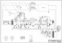
High-performance hollow state was never easy or cheap (or lightweight). Note the multitude of plate chokes, the 1950s current sources.
Actually, no, I do think these are the turns ratios after all. Output impedance is specified at around 40 ohms but that's clearly a plate output (so a few kOhms typ - but then again, there is negative feedback going to the previous stage), and the input transformer has a shield winding (plus what I assume is a mu-metal shield, not unexpectedly). Plus if you think about it, 1:30 would get input voltage noise right in the vicinity for a good mic amp (1-2 nV/√(Hz)).I looked up the old IRT V 76 module, and they say 1:30 on the input and 9:1 on the output - these could be impedance ratios though, which would amount to 1:5.5 input and 3:1 output turns-wise.
High-performance hollow state was never easy or cheap (or lightweight). Note the multitude of plate chokes, the 1950s current sources.
Attachments
Last edited:
How about replacing the input 100k with a pot and removing the bypass cap on the first triode?
Another idea, I used to have an old mono FM tuner and preamp combo that had a dual ganged volume control. The 100k input resistor would be one half of the pot and the 1Meg the other half of the pot.
The input transformer likes to see 10K, so try replacing the 100K resistor with 10 or 20K resistor or pot.
I thought the point was less noise, not more...How about replacing the input 100k with a pot and removing the bypass cap on the first triode?
I will wire the Input transformer to 1:5. I will probably have less noise like this.
Try this with the existing 1M pot in circuit. This may work just fine for you then.
Since the gain will be even greater than before, you could remove C2 to bring it down.
Last edited:
- Home
- Source & Line
- Analog Line Level
- Is there a way to reduce signal without divider ?