Hello.
I want to lower a signal without using a voltage divider, it is noisy, especially when you have to use high resistor values to get a very low signal.
So I was wondering if it is possible to to it with transistors without loading an opamp too much. And with lower noise than a divider.
Thank you.
I want to lower a signal without using a voltage divider, it is noisy, especially when you have to use high resistor values to get a very low signal.
So I was wondering if it is possible to to it with transistors without loading an opamp too much. And with lower noise than a divider.
Thank you.
It's best to post your circuit, much depends on the details. How much attenuation?
With an op amp, the gain could be changed instead.
With an op amp, the gain could be changed instead.
I want to lower a signal without using a voltage divider
Yes.
Inverting stage with gain less than one.
2k input will be enough silent and driveable by most opamps without significant thd rise
But provide special attention to keep stage stable.
Only with a transformer, but they are expensive and may not work at the frequencies you want. Therefore, you are stuck with a divider.
Can you make the divider better? Yes.
The guys have provided ideas using op-amps, buffers, followers, etc.
Best, Sandro
Can you make the divider better? Yes.
The guys have provided ideas using op-amps, buffers, followers, etc.
Best, Sandro
Hello.
I want to lower a signal without using a voltage divider, it is noisy, especially when you have to use high resistor values to get a very low signal.
So I was wondering if it is possible to to it with transistors without loading an opamp too much. And with lower noise than a divider.
Thank you.
You mention an opamp. Opamps can drive low impedance loads without difficulty and so I'm puzzled where your 'high resistor values' figure into all this.
Are you thinking you have to add a high value resistor in series with whatever you are feeding ?
An NE5532 opamp for example can drive as low as 600 ohms and so a divider using lets say 910 ohm and 1 ohm would get you a signal level of just 1 millivolt for 1 volt input and all at a very low noise level, effectively just the noise level of the 1 ohm plus noise from your earlier stages that has been attenuated by the divider. It doesn't get much lower than that.
Thank you guys for the help.
Sorry I wanted to say "gainstage", not opamp.
I posted this late at night, and was looking at TI opamps datasheets...
Opamp I can't use because it's an ecc83 fully bypassed (to lower the impedance). Opamps can only accept 30 to 40V max input, or is there a trick ?
Transformer might do the job. It's at audio frequency for a microphone preamp tube.
I want to replace the 1M potentiometer here (But I have 220V at B+2 and I modified the output stage) :
Last edited:
If you want to replace the 1M pot with an attenuator, just use two resistors.
Why are you ruling out a voltage divider, this is a perfectly good approach.
If you want variable attenuation, keep the pot. The motivation here is not clear.
Why are you ruling out a voltage divider, this is a perfectly good approach.
If you want variable attenuation, keep the pot. The motivation here is not clear.
Make R4 180k and P1 100k perhaps? No grid-stoppers for V1 ?
You can use a capacitive divider, but they are not easily variable, and need a low impedance drive to work at HF.
You can use a capacitive divider, but they are not easily variable, and need a low impedance drive to work at HF.
 moved to analogue line level.
Thank you. Motivation is lower noise possible 😉
Variable if possible, but I don't care because I will use it for my personal use.
So I don't need to make it variable, I only have one microphone.
Thank you Mark, I wanted to just lower P1 value but then I said "maybe I can do even better", So I asked you guys.
So the best way is a follower/buffer/opamp with a low value value resistor divider.
I will do it and report, I start with a High voltage mosfet as follower, with a low value potentiometer.
If you have any info on parameters to look for in low noise HIGH voltage mosfet in the datasheet (or acticles) please tell me ?
Thanks again, your help is really appreciated.
Where the follower will go, the noise of the input tube stage (which may be anywhere from 40-100 nV/√(Hz) or so) has already been amplified by a little less than µ. I very much doubt that you are even going to find any part that would add substantially to that.
Would you possibly have any suitable type already in the box? Vds >= 250 V or so, Id <= 0.5 A perhaps, Rdson uncritical (but generally higher in devices suitable for linear operation), Vgs no higher than 20 V and preferably less, and some half-decent power dissipation to support maybe 2 mA at least, otherwise you might get stuck with a 1Meg pot yet again.
At this point I am wondering whether the pot even is that much of a limiting factor. Yes, worst-case source impedance is 500k (or 90 nV/√(Hz) at room temperature), but that's at -6 dB, where you'd still have plenty of noise coming in from the previous gain stage. At -20 dB we're down to 38 nV/√(Hz), but I reckon the input stage still contributes more than that. At -30 dB and about 22 nV/√(Hz), next-stage tube noise is going to dominate.
You may be better off tackling the input gain stage. Maybe use the input tube as a cascode for a small JFET instead (heresy!). What is the turns ratio (or impedance ratio) on the input transformer? (Any other data, like winding R?) What is plate current like right now? Using a current source instead of the 100k plate resistor may be worth considering.
Well, at least for the high gain setting. The low gain setting may be a different beast (but would you use that when you need lowest noise?). Then we should also look at the next stage.
And yes, I find the complete lack of any gate stopper resistors equally as concerning as Mark Tillotson does.
Last edited:
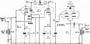
Grid stopper for v1 will add noise. If I pick up radio I will add one, but now I only care about noise. What value would you recommend 1K ?
The follower will go between the V1 V2, in place of the potentiometer. You can forget the LO input I removed it. When I use the pot I always have around 600k in series with the signal.
With a transformer, I am afraid to pick up too much magnetic, because in this chassis I have a full 50 power transformer and a choke (it's an old gutted out traynor amp).
I use the amp to experiment. I mainly use it as a power supply.
The transformer is a 1:2.5 ratio.
NOTE : I have to lower the signal A LOT, Is it better to do it before or after the last stage ?
After for SNR ?
EDIT : Thank you Ketje. I will try.
Last edited:
- Home
- Source & Line
- Analog Line Level
- Is there a way to reduce signal without divider ?