Higher Hfe would give more gain, and input sensitivity is already highish.
More important to pair the transistors for minimum offset.
More important to pair the transistors for minimum offset.
Hi,
The input KSA992 should be matched for Hfe so that the output DC offset is minimal.
But is there a reason to go for lower or higher Hfe ?
The question came up because at Mouser you can buy the KSA992 in different classifications:
FA: hfe2 300 ~ 470
FB: hfe2 430 ~ 600
Grts,
Danny
Hi X,
Whilst what danny says above is the "ideal case", I thought R113 was there as the adjustment you use, to get a <10mV offset result?
Matching the transistors is an expensive job - you probably have to buy 30 or 40, in order to end up with a matched pair (and by matched pair, I mean Hfe a max of 5 apart).
Andy
100 pcs. 2N5401 for a little over € 2,- seems not so expensive....
2N5401 DIOTEC SEMICONDUCTOR - Transistor: PNP | bipolaire; 150V; 0,6A; 625mW; TO92; 2N5401-DIO | TME - Elektronische Componenten
2N5401 DIOTEC SEMICONDUCTOR - Transistor: PNP | bipolaire; 150V; 0,6A; 625mW; TO92; 2N5401-DIO | TME - Elektronische Componenten
xrk971, have you or any other builder have plans to test this class A amp using the FTC method of testing? 5 minutes of full power onset of clipping?
as you know, Mark Levinson has a 25 watt class A, much bigger and heavier than your amps, i wonder how yours compare...
as you know, Mark Levinson has a 25 watt class A, much bigger and heavier than your amps, i wonder how yours compare...
On an ammo belt I can usually get 2 to 3 pairs in a dozen. They are not expensive and I buy maybe 50 at a time. But just buy a dozen or so and you should be set. The resistance adjustment does not provide auto temperature tracking provided by a matched pair thermally bonded together.
Last edited:
xrk971, have you or any other builder have plans to test this class A amp using the FTC method of testing? 5 minutes of full power onset of clipping?
as you know, Mark Levinson has a 25 watt class A, much bigger and heavier than your amps, i wonder how yours compare...
Sure, Tony - I’ll get right on it. On a Class A like Alpha Nirvana, the current flowing through the transistor is the same regardless of time spent at clipping. It’s not going to thermally stress the amp any more than idle. In fact, the outputs might be cooler at full power as less dissipation through the MOSFETs but more out the load resistors. I have a fan cooled 300w EBG resistor. I’ll connect it for the 5 minute at clip onset test. What are you hoping to see? Should I take an OScope shot at 0min and 5min and compare?
Being single-ended class-A, the load can't ever get more power than the bias, so the full power test should actually let the amp run a bit cooler as all the bias current is put into the load, instead of the heatsinks. 😀
EDIT - I see X answered it the same time I was typing.
EDIT - I see X answered it the same time I was typing.
Sure, Tony - I’ll get right on it. On a Class A like Alpha Nirvana, the current flowing through the transistor is the same regardless of time spent at clipping. It’s not going to thermally stress the amp any more than idle. In fact, the outputs might be cooler at full power as less dissipation through the MOSFETs but more out the load resistors. I have a fan cooled 300w EBG resistor. I’ll connect it for the 5 minute at clip onset test. What are you hoping to see? Should I take an OScope shot at 0min and 5min and compare?
thanks, people should understand that any amp is just as good as the power supply components you put into building it, so different sizes of power traffos may yield different results, no matter that it may be small..
a sine wave source, 1khz test frequency, 8 ohm dummy resistor loads and a scope....this testing confirms what you have calculated as the power output..
Being single-ended class-A, the load can't ever get more power than the bias, so the full power test should actually let the amp run a bit cooler as all the bias current is put into the load, instead of the heatsinks. 😀
EDIT - I see X answered it the same time I was typing.
that is the theory, actual testing will reveal by how much, now is a good time to learn that much..
class A have efficiencies not higher than 50%, theory says...
Hi,
The Alpha4R that I'm listening now will be upgraded to the Nirvana.
I'll be using the same case and PS, so the change will be easy.
Since my PS is 25V I opted for the 8R version.
Of course I had to play a little in LTspice to see the outcome of putting a 4R load on the 8R Nirvana.
With normal bias at 1.65A and 15vpp the output currents I(R141) I(R142) are out of balance and the negative is clipping.
But when I augment the bias to 1.93A (0.18r) it's nicely balanced, no clipping with 15vpp and 4R.
So 1.93A seems a nice alternative.
Now I only need the blessing of Hugh or X 🙂
Regards,
Danny
Attachments
Being single-ended class-A, the load can't ever get more power than the bias, so the full power test should actually let the amp run a bit cooler as all the bias current is put into the load, instead of the heatsinks. 😀
EDIT - I see X answered it the same time I was typing.
Quoting your colleague Sangram: .... it's a SE amp, operated in PP.
Hugh Dean, the designer: it's SRPP (series regulated push-pull).
Kokoriantz: it's SRPP....
Tony - I completely agree. 😀
I have done it with a FirstWatt Aleph J (400VA transformer linear PSU) and the heatsinks dropped by 3-4C.
I have done it with a FirstWatt Aleph J (400VA transformer linear PSU) and the heatsinks dropped by 3-4C.

Daanve
Stop. You have been politely warned about your constant comments on the operation of this amplifier. Start a new thread if you want to continue, do not discus it here.
Last edited:
Tony - I completely agree. 😀
I have done it with a FirstWatt Aleph J (400VA transformer linear PSU) and the heatsinks dropped by 3-4C.
by doing the FTC testing we will learn more, and perhaps put to rest some of Danvee concerns...
a pp amp will have an efficiency of 64% or more...
100 pcs. 2N5401 for a little over € 2,- seems not so expensive....
As far as I can see from the circuit - attached - 2N5401 does not appear. 😕
Danny was talking about KSA992 (although, no, these are not expensive).
Andy
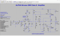
Hi Danny,
I examined your schematic and you are almost there.......
If you reduce the two 0.18R source resistors to 0.15R each you will increase the quiescent to 2.3A. With 24V rails, you will dissipate 110.4W, but if you have enough cooling with your LARGE mosfets there will be no issue.
Add a 100p ceramic NPO of 47pF from base to collector of T4. This removes a glitch at MHz level when the transistor is coming off top clip.
You will then find that with 24V rails and 2.3A quiescent you can reach 36Vpp into a 4R load, which is no less than 40.5W and THD of 0.0413%!
I think you will be pleased with this........
Hugh
Hi Hugh,
2.3A is too much for my heatsinks, I like to keep it at 1.93A.
36vpp is not needed for me, 4vpp is already crazy loud on my speakers.
I'll add 100p around T4.
Thanks!
2.3A is too much for my heatsinks, I like to keep it at 1.93A.
36vpp is not needed for me, 4vpp is already crazy loud on my speakers.
I'll add 100p around T4.
Thanks!
As far as I can see from the circuit - attached - 2N5401 does not appear. 😕
Danny was talking about KSA992 (although, no, these are not expensive).
Andy
100 KSA992 for $7.30
KSA992FTA ON Semiconductor / Fairchild | Mouser
Either 5401 or 992 will work. Just make sure legs are correctly aligned.
- Home
- Amplifiers
- Solid State
- Alpha Nirvana 39w 8ohm Class A Amp