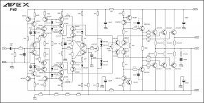
no it's the F40 that has a mosfet at the entrance
Can you post the schematic for the F40 please?
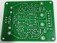
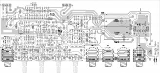
A Class PSU first image prototype boards
hi guys the A Class PSU PCB are done I hope this prototype PCB work the first try sadly the 2SK246 N FET are hard to find and can some one post image of the real semiconductors? I have seen some on EBay but I'm so aware that they might be counterfeit parts 🙁
or a list of similar ones that I can use
anyway here are the images of the PCB 🙂
Attachments

Can you post the schematic for the F40 please?
Attachments
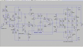
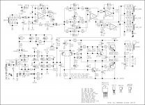
In last post I forget about the schematic of B50. Now here is B50 schematic picture.
Regard
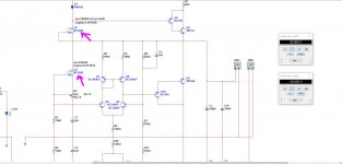
Looks very much like the alexanderamp.
I have done one years ago, I have still the schematic with dynamic bias build in after build the first one, did sound quite beautifull for such a bipolair amp, did use the opa627 opamp that time....
Maybe this schematic is of use for more ideas, like the bias, it is free.
regards
Attachments
hi guys the A Class PSU PCB are done I hope this prototype PCB work the first try sadly the 2SK246 N FET are hard to find and can some one post image of the real semiconductors? I have seen some on EBay but I'm so aware that they might be counterfeit parts 🙁
or a list of similar ones that I can use
anyway here are the images of the PCB 🙂
BF244A or BF245A but keep an eye on the pinout. Maybe other suffix like B or C will do with few changes on trimmer and 15k resistor value.I also found a usefull elaboration by a member that will be helpful:
Although I am not responsible for this thread some member asked me for help -
his build is not working properly. As I do not know the background, his working
skills, equipment etc and so it may be OK to give a short explanation how the
shunt regulator of post 1 works.
I feel it is worthwhile, because this is a straightforward design. I did not build it
but I am sure it works properly. As always it can be simplified and made more
complicated at the same time.
This regulator is symmetric, for positive and negative input and output. For
explanation it is sufficient to look at one side only: upper half, positive.
Upper third of this is a constant current source formed by a three diode
reference, pass transistors and sensing resistor, 22 ohms here. A simple
JFET current source feeds the diode string. A complementary darlington,
sometimes referred to as Sziklay pair is used to pass the current and is
effectively working as pnp.
The current through this source is given by (Vd - Vbe)/Re, a two diode drop
divided by 22 ohms here, so about 55 mA. This current can be increased by
decreasing the 22 ohms resistor value and vice versa.
Error amplifier is of the differential pair type. The BC546 pair has a current
mirror as active load.
Reference voltage goes to the positive input. It is established here by a constant
current through a resistor (15k) and cleaned up with 1µ cap. The lower JFET is
the current source for this. This current is adjustable by potentiometer (1k here)
in order to change the reference and hence the resulting output voltage.
Negative input of the error amp senses the output via 22k and 15k divider pair
resistors.
Error amp drives shunt transistors, a standard darlington pair.
Formula for output voltage is Vref•(1 + Ru/Rl) - upper and lower resistor of the
divider pair - it is 2.5•Vref in this case.
So for instance if your reference voltage is 8 volts established by about 0.5mA
through 15k, the output voltage of the regulator will be 20 volts.
If we assume the circuit is set up properly with working parts and carefully fired
up for the first time, preferably with variac, current limiting lab supply or current
limiting resistors, some precautions apply:
If you use a JFET in the lower place, for the reference input, which has unsuitable
characteristics, a wrong reference voltage will be developed and the regulator will
not work. If the reference is too high, if will go to full voltage, if it is too low the output
can not be adjusted properly.
So in order to check operation of the regulator, replace the left 15 k resistor with a
zener diode first. A zener of 8 volts will give output of 20 volts as calculated above
if the regulator dc input is high enough for this.
As a second step replace the zener with a 1k resistor in order to check the JFET
current, it is voltage over this resistor divided by 1k in mAmps. Check the regulator
output at the same time, it should again be 2.5 times as high. Then you can decide
to use a suitable resistor instead of the 15k or use a different potentiometer to suit
the JFET drain current. It is not necessary to stick to 15k, better change this one
instead of hunting for FETs or changing or readjusting the FET potentiometer to death.
Good luck.
Last edited:
BF244A or BF245A but keep an eye on the pinout. Maybe other suffix like B or C will do with few changes on trimmer and 15k resistor value.I also found a usefull elaboration by a member that will be helpful:
thank you wow a lot of data information I will follow your suggestions 🙂
thank you wow a lot of data information I will follow your suggestions 🙂
Hi Vargasmongo, someone told me about BF256B, but I dont know if it work.
Hi Vargasmongo, someone told me about BF256B, but I dont know if it work.
good think is available to purchase from Mouser and I used on my simulation and actually work fine "on simulation" I'm not sure if this is gonna react the same in real time, the downside is that the pins are not the same is okay I don't mind at all
anyway I will follow your advice guys 🙂
Attachments
hi guys the A Class PSU PCB are done I hope this prototype PCB work the first try sadly the 2SK246 N FET are hard to find and can some one post image of the real semiconductors? I have seen some on EBay but I'm so aware that they might be counterfeit parts 🙁
or a list of similar ones that I can use
anyway here are the images of the PCB 🙂
Counterfeit parts don't necessarily mean they don't work. Many work fine. I would try them before I just dismiss them. They are cheap enough to give them a try.
Counterfeit parts don't necessarily mean they don't work. Many work fine. I would try them before I just dismiss them. They are cheap enough to give them a try.
you right, I'm gonna order some 🙂
not all parts are counterfeited, parts that sell very cheap are not worth it to counterfeit, but parts that are high in "demand" and are high in cost are...
re bias setting adjustments, please recheck your bias when the heatsinks are warmed up sufficiently...bias starts loe when sink temps are low but climbed higher with temperature...
re bias setting adjustments, please recheck your bias when the heatsinks are warmed up sufficiently...bias starts loe when sink temps are low but climbed higher with temperature...
not all parts are counterfeited, parts that sell very cheap are not worth it to counterfeit, but parts that are high in "demand" and are high in cost are...
re bias setting adjustments, please recheck your bias when the heatsinks are warmed up sufficiently...bias starts loe when sink temps are low but climbed higher with temperature...
make sense a cheap part that is not gonna generate money is not worthy to be counterfeited "I didn't see it that way yes" bias oh yes absolutely I will check that out too 🙂 I order just a few just a few hours ago
Yeh i got some from the JCLPCB site but i miss the A17,A23 and A33. I want some nice looking and good quality pcb so need Gerber file so that i can order at this siteHi surjitsharmaph.
All the required files and a list of A40 items are listed in the information below the video.
In my opinion, the best playing amplifier.
YouTube
Yeh i got some from the JCLPCB site but i miss the A17,A23 and A33. I want some nice looking and good quality pcb so need Gerber file so that i can order at this site
Here are A33 Gerbers. I don't have the others. I built the A33 using these so I know they are good.
Attachments
- Home
- Amplifiers
- Solid State
- 100W Ultimate Fidelity Amplifier