Looks ok .. datasheet shows Vbe typ. 0.6V at 1mA, hfe typ. 350. Doesn't look too far out, but your gain is now low (about 100)!
So Vbe could be OK then. It just sounded very high at 0.6V.
Just looking at the gain again 🙂
The hFE does come in at around 327. Here is just over 20ma flowing in the collector for 61uA base current. Vbe now 700mV.
Attachments

Well now...
That explains a lot. I just assumed the model posted was for another Geranium... mea culpa 🙂
That explains a lot. I just assumed the model posted was for another Geranium... mea culpa 🙂
I would also include RE and RC every time. These could be determined from the Vbe (indirectly) and Vce (sat) voltages.
I've never been able to figure out a way to split up RB and RE. Normally I just apply RB from Vbe data at higher current. Same for RC using Vce(sat). Don't know what to do about RE. You have any ideas? For the AC128, setting RE = RB / BF ended up giving seemingly better results, although I'm not sure why.
Hagtech - do you allow for temperature effects in IS?
I believe that would require multiple models. Thermal effects do take place in a sim if you specify TNOM, but my models always target typical characteristics at 25C.
Just realized, maybe I should have set EG=0.67 for the AC128 instead of EG=1.11? I'm wondering how that might change things...
I agree that separating RB and RE can be difficult. While you can generate basic SPICE parameters from datasheets, quite a few of the others need info which is not there. In the past I've used iteration on RB and RE to give a best match, but as RB changes with current it's a difficult challenge. Usually RBM can be found but RB then needs an educated guess (and check in the simulator).
On the other hand, they can be measured relatively straightforwardly with the right kit and setups. And it you have the transistors to hand which you want to use ...
On the other hand, they can be measured relatively straightforwardly with the right kit and setups. And it you have the transistors to hand which you want to use ...
Regarding the temperature, not you don't need multiple models, because SPICE will calculate the effects of temperature on the device characteristics. What is needed is that the measurement temperature is taken into account when setting the models. It can be tricky because there are also various levels (model options) which use different expressions, so normally a device would be characterised against a particular option.
I've never been able to figure out a way to split up RB and RE. Normally I just apply RB from Vbe data at higher current. Same for RC using Vce(sat). Don't know what to do about RE. You have any ideas? For the AC128, setting RE = RB / BF ended up giving seemingly better results, although I'm not sure why.
RC, RB and RE in datasheet are the die (intrinsic) resistances. The representation of RE on the base is beta (hFE) * RE, rendering in RBE. The total base resistance sums up to RB + RBE. Keep in mind that an external Re yields to Rb-total = RB + beta * (RE + Re). With an external Rb even:
Zb = Rb + RB + beta * (RE + Re).
Also can the total Zb (RB + external Rb) 'seen' at the emitter as part of the total Ze:
Ze = { (Rb + RB) / beta + RE } // Re.
Notice the "//": parallel!
Next course: More fun with math!!!
Actually the voltage drop across the emitter resistor is (hFE+1)*RE (the emitter current).
But again the issue is that at low bias currents where the volt drop across RE is small, the effective base resistance, usually designated by RBB (the internal resistance from the base lead to the inside of the base) is its highest (RB). At currents where RE might affect the base voltage, charge modulation of the base reduces RB hence at highest currents, RBM is the limiting value (the "real" extrinsic base resistance between the inside base and external contact).
It usually takes a bit of maths to sort out.
You can get some idea from knowing IS what the expected Vbe should be (internally) for a given current. Using some high current info that will give an idea of the combined RE, RB voltage drops when multiplied by the appropriate currents. Whether you can extract RB at low currents I'm not sure. It would need very accurate measurements/data.
Mars gives a hint- RB is usually measured using high frequency gear.
Mars gives a hint- RB is usually measured using high frequency gear.
Here is a suggestion. If you have access to a data set with low to high currents (the Gummel plot, in other words - but nearly every datasheet I have seen, where there are plots, show linear Ic and Ib versus Vbe, inexplicably. Perhaps manufacturers didn't want you to see low gain characteristics), you could try using Newton-Raphson iteration to calculate a set of RB and RE terms. There should be only one RE, but there may need to be several RB values to cover the moving target. That means taking Vbe at a number of points and using the corresponding Ic and Ib data. I haven't tried this myself (I prefer measuring RB) but with, say, 10 points covering what might be RB to RBM it might be possible to solve these simultaneously. THe last data point should be the highest possible current reading.
I've never seen any datasheet publish a Gummel plot. Sure would be useful! I'm still stuck with:
Zb = RB + (BF + 1)*RE
One equation, two unknowns. That's why I usually set RE = 0 and use RB to cover the Vbe losses. Now I see this RBM parameter you pointed out (didn't used to be there when I last dug into this stuff in the early 90's), and yes it may be more appropriate than RB. For most simulations however (not trying to reverse-avalanche BE junction, inverting transistor (swapping E and C), or running negative base current), RB alone works just fine. That's where I ended up.
When I'm modelling in AimSpice, these parameters are of importance (to me) to forge reliable models:
BF: Ideal maximum forward beta
IKF: Corner for forward beta high current roll-off
VAF: Forward Early voltage
VAR: Reverse Early voltage
RB: Zero bias base resistance
IRB: Current where base resistance falls halfway to its minimum value
RBM: Minimum base resistance at high currents
RE: Emitter resistance
RC: Collector resistance
CJE: B-E zero bias depletion capacitance
CJC: B-C zero bias depletion capacitance
Most parameters correspond with specifications in datasheets, but not all.
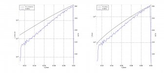
Gummel plot
Attached is a Gummel plot of a NOS AC127. The data is available as an XLS file. It is too large to post here. You can send me a pm for the spreadsheet.
The beta calculation is noisy due to the base current measurement uncertainty and/or noise pickup in the unshielded cabling close to the transistor.
If other measurements are needed, just post your request here.
Attachments
One equation, two unknowns.
That is why I suggested you would need several data points. I made an assumption that at high currents, RBB would be at the value of RBM and as RE is constant (or should be) that would give you two equations. Once RBM and RE are found the rest would be simpler...
What is not known is the current at which RBB reaches its minimum, at least not without a measurement, and whether the datasheet values give the info needed.
That is indeed the trouble with trying to extract SPICE models from the datasheet. Often you have to go and measure something in the end.

Thanks! Lot's of interesting models!
- Home
- Amplifiers
- Solid State
- New Germanium PNP Transistor SPICE Model