A good start to generating SPICE models for these old devices.
Remember that the collector capacitance is not usually quoted at Vcb=0, but SPICE needs the zero bias value. As a start the power law could be taken as the theoretical square root but tends to be below 0.5 on many Si devices.
I'm guessing you have an AC128 you could measure? That would at least allow a few more parameters to be determined. IIRC (I may be wrong here) BR tended to be higher than 1 for old Ge devices, and a measurement would be relatively quick to check.
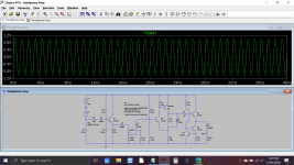
😎 thanks... it works for me in my Germanium headphone amp simulation with all the original resistor values used in the real build.
GERMANIUM Single ended Class A Headphone Amp.
GERMANIUM Single ended Class A Headphone Amp.
Attachments
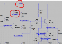
Yes, that's the circuit (right of volume) I copied to build... just taken from the shelf (some dust... cough) and with different parts: AC125, AC130 (npn!), AC132, 2 x AC124K.
Kind request to hagtech if corresponding models can be generated (pm).
I shall post circuit, AimSpice simulations and analysis accordingly.
Kind request to hagtech if corresponding models can be generated (pm).
I shall post circuit, AimSpice simulations and analysis accordingly.
I'd be happy to make whatever model you'd like - as long as you can supply a complete data sheet (all the graphs).
🙂
🙂
Thanks!! I happened to have a GE plan open in Pspice. I had another AC part model; yours drops in and runs with less difference than I would expect across a bagful of Germs.
For those who can't copy/paste from PDF:
[special=*AC128 PNP Model by Jim Hagerman
.MODEL AC128 PNP
+(
+ BF = 90
+ IS = 17u
+ RE = 220m
+ BR = 100m
+ VAF = 30
+ ISE = 190n
+ TF = 106n
+ TR = 10u
+ CJC = 100p
+)
------------------------------
* AC128 PNP Model by Jim Hagerman
* "+" signs removed for old Pspice
.MODEL AC128 PNP (
BF = 90
IS = 17u
RE = 220m
BR = 100m
VAF = 30
ISE = 190n
TF = 106n
TR = 10u
CJC = 100p )
*]%[/special]
As a user of AimSpice, I have to translate the 12AX7 model.
I've requested for full datasheets of various Ge types along the line.
I'll pm them when available.
I've requested for full datasheets of various Ge types along the line.
I'll pm them when available.
Another oldie used in pedals...
.model _bc108c npn
+(
+ bf = 320
+ is = 60e-15
+ rb = 20
+ vaf = 30
+ ikf = 100m
+ ise = 100e-18
+ tf = 500n
+ tr = 1u
+ cjc = 3p
+)
.model _bc108c npn
+(
+ bf = 320
+ is = 60e-15
+ rb = 20
+ vaf = 30
+ ikf = 100m
+ ise = 100e-18
+ tf = 500n
+ tr = 1u
+ cjc = 3p
+)
RB = 20? You sure? That would be very low for a wee little relatively high beta small-signal NPN. Among oldie types, 2N4403 is about the only one that gets this low IRL. I would be expecting more like a couple hundred ohms.
As the BC107/108/109 family suvived as BC237/238/239 and BC547/548/549 eventually, I'd expect the models of the latter ones also to fit to the veterans.
Best regards!
Best regards!
Yeah, RB=20 is a bit low. I use this parameter to adjust Vbe curve at higher currents (IS sets low current values). Model works quite well up to tens of milliamps collector current, which is where I was focused.
sgrossklass - you were so right! I re-did RB calculation based on Vbe plot (instead of numbers printed in datasheet), and it came out much higher at RB=180. That might not be best value for noise simulations, but for Vbe and Ic response, the model is spot on up to at least 100mA. Thanks for the suggestion.
.model _2n5088 npn
+(
+ bf = 350
+ is = 70f
+ rb = 110
+ rc = 1
+ br = 5
+ vaf = 50
+ ikf = 100m
+ ise = 0.2f
+ tf = 3n
+ tr = 100p
+ cjc = 10p
+)
+(
+ bf = 350
+ is = 70f
+ rb = 110
+ rc = 1
+ br = 5
+ vaf = 50
+ ikf = 100m
+ ise = 0.2f
+ tf = 3n
+ tr = 100p
+ cjc = 10p
+)
I would use RB and RBM parameters as the base resistance will vary with current. Your rb of 20 might be better as an RBM figure.
I would also include RE and RC every time. These could be determined from the Vbe (indirectly) and Vce (sat) voltages. Note that the only parameters which stop excessive currents are these resistances.
I would also include RE and RC every time. These could be determined from the Vbe (indirectly) and Vce (sat) voltages. Note that the only parameters which stop excessive currents are these resistances.
What current is the 5088 working at?
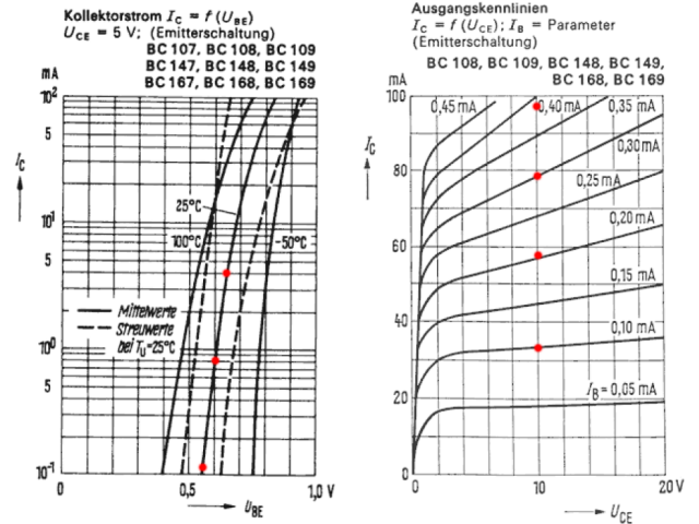
From the devices I have evaluated old (Mullard) BC108 types had Vbe=0.62V at 1mA. Moderns (On Semi) BC547's have Vbe=0.65 at 1mA. Hagtech likes working from the datasheet so typical results from (old) datasheets might be where his IS has come from.
@Hagtech - do you allow for temperature effects in IS?
Datasheets often quote at 25C while SPICE models generally use 300K as TNOM. The difference isn't huge but may be a few mV.
In my sim? Its very low, about 4.5uA according to the sim and 1.4mA emitter current. Sounds like the gain is a bit high perhaps.
Edit... silicon runs at 13uA base current.
Edit... silicon runs at 13uA base current.
Looks ok .. datasheet shows Vbe typ. 0.6V at 1mA, hfe typ. 350. Doesn't look too far out, but your gain is now low (about 100)!
- Home
- Amplifiers
- Solid State
- New Germanium PNP Transistor SPICE Model