Got the Studer PSU directly from China and its a nicely finished sturdy box. I liked it immediately, everything sounds little bit more relaxed and flowing in the aesthetics of modern boring DAc's for old duchebags. Good enough but
nowhere near Theta Gen V or even ARC DAC 2 dynamics and life.
nowhere near Theta Gen V or even ARC DAC 2 dynamics and life.
Yes, it looks the right picture. I got this one.Is this studer boards you guys talk about?

5-28V STUDER900 Regulator Power Supply Board Can Assembled Into Double Power 4F3 194452680023 | eBay
I opt for the kit so that I can test the parts before assemble. You can get assembled PSU for a few dollars more.
Check out the original thread on the Studer900 clone.
low noise Pre-Amp / DAC power supply MJE15034 TL072 Regulator based on STUDER 900
Last edited:
Yes , I bought the single voltage version of this PSU . At $50 plus shipping for complete PSU in a nice sturdy alu chassis there is really no incentive to DIY that thing.
I just regret it took mi so long (several months) and the DAC became so obsolete that it's almost unplayable. I mean, I took it out of the box and it's lost half of it sonic potential before I even hooked it up because three generation of new DAC's appeared on the market during that moment. My next DAC goes to the dumpster before I take it out of the box.
I just regret it took mi so long (several months) and the DAC became so obsolete that it's almost unplayable. I mean, I took it out of the box and it's lost half of it sonic potential before I even hooked it up because three generation of new DAC's appeared on the market during that moment. My next DAC goes to the dumpster before I take it out of the box.
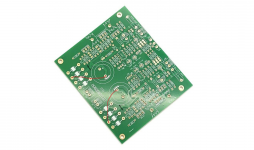
The PCB layout on the Studer900 leaves quite a lot to be desired, look at the charging current paths (and what else is connected to them) between the rectifiers and input capacitors as an example of how not to do it. There are probably a lot of other things I can't see.
It's a crapshoot.
It's a crapshoot.
it's lost half of it sonic potential before I even hooked it up .
Are you saying it sounds worse than when you bought it?
Appreciate your comment. I don't have enough knowledge to understand it. Can you elaborate more and suggest how to modify the board? A magic marker markup on the PCB trace picture will help a lot.The PCB layout on the Studer900 leaves quite a lot to be desired, look at the charging current paths (and what else is connected to them) between the rectifiers and input capacitors as an example of how not to do it. There are probably a lot of other things I can't see.
It's a crapshoot.
Can you also repeat your comment at the original Studer 900 thread too.
low noise Pre-Amp / DAC power supply MJE15034 TL072 Regulator based on STUDER 900
The area around the rectifiers can also use some help. Not much more you can do without really understanding the design. I can only see so much from those photos. It's not a good PCB design, cannot vouch for the quality of the electrical design.
Here is an example of something I would fix. You can run jumpers on the bottom of the PCB so it's not ugly. (Cut where you see black)
Here is an example of something I would fix. You can run jumpers on the bottom of the PCB so it's not ugly. (Cut where you see black)
Attachments
low noise Pre-Amp / DAC power supply MJE15034 TL072 Regulator based on STUDER 900

This is one of the few PSU offer on e-bay that had been commented extensively and received generally positive feedback on sound effect. I am sure clone PCB cuts corner and can be improved.
The area around the rectifiers can also use some help. Not much more you can do without really understanding the design. I can only see so much from those photos. It's not a good PCB design, cannot vouch for the quality of the electrical design.
Here is an example of something I would fix. You can run jumpers on the bottom of the PCB so it's not ugly. (Cut where you see black)
What's your input voltage to the reg?
Tr1 & 2 provide a very basic regulator to power the TLO72 at approx 10V (referenced to VCC), which is the datasheet minimum. With an input voltage < about 11V the circuit may not work properly.
0.5R will give you a current limit of about 1.2A (VBE/0.5).
The Ebay board follows the Studer schematic fairly closely except the reference voltage is derived from an LED instead of the original zener. They also added an extra decoupling cap or two and simpliified the pot chain a bit. The pcb layout is rather poor and the schematic (as above) could be a lot more logically drawn!
This is one of the few PSU offer on e-bay that had been commented extensively and received generally positive feedback on sound effect. I am sure clone PCB cuts corner and can be improved.
Some PCB mod suggested by bButcher.


My is a single power version, if you have a dual power version, the layout is almost the same, at least the power lines part.
Are you saying it sounds worse than when you bought it?
I was joking Nezbleu. My GF says that I should stop since nobody gets my jokes cuz my Syntax sucks😀, but she is an American so I wasn't paying any attention.... Now, I see even Canadians don't get it so I have to re evaluate.
My Dac is Antelope Zodiac Gold , a mastering dac which stocks came with $5 SMP psu at ~$4k a few years ago. Equally Bulgarian PSU called Voltikus (+18V 1A) which they sell separately costs $1.2k. I was using the DAC with that SMP PSU and decided to replace it with Chinese supply. I think it sounds better with that Studer clone and costs peanuts..
Some PCB mod suggested by bButcher.
Does paralleling Shottky rectifiers with caps really helps? Is this an empirical mod, confirmed by measurements or just feel good measure ?
I believe I have the same board in my unit
Where did you get the idea that the rectifiers are Schottky (not shottky)?Some PCB mod suggested by bButcher.
Does paralleling Shottky rectifiers with caps really helps? Is this an empirical mod, confirmed by measurements or just feel good measure ?
I believe I have the same board in my unit
Read the Quasimodo or Cheapmodo threads and forget about parrallel cap snubbing of the bridge diodes or shotkeys
Plus if there was a reason to do it (RF rectifier hash) X7R ceramics are way better than films for this and a 0.01uF is generally enough.
Points well taken.Plus if there was a reason to do it (RF rectifier hash) X7R ceramics are way better than films for this and a 0.01uF is generally enough.
What is your comment on the other trace mod by bButcher?
They look worthwhile from what I can tell. The one that loops around the transistor I would find a way to shorten. (Rather than loop around cut that trace and go directly.)
I would probably run 24 awg bus wire or similar along those traces. (Add teflon sleeve for insulation or use magnet wire)
I would probably run 24 awg bus wire or similar along those traces. (Add teflon sleeve for insulation or use magnet wire)
Where did you get the idea that the rectifiers are Schottky (not shottky)?
I vaguely remember that the description said they were shottky rectifiers.
There was no mention of Schottky in the original thread.I vaguely remember that the description said they were shottky rectifiers.
low noise Pre-Amp / DAC power supply MJE15034 TL072 Regulator based on STUDER 900
I have no idea what "shottky rectifiers" is. Can't find it in any dictionary.
- Home
- Amplifiers
- Power Supplies
- Ultra low noise PSU on e-bay