For a near field design, it sounds like the polar is priority. So if steep improves that, then it would be a sacrifice for the greater good.
There are of course other crossovers possible that have a gentler "knee" and that have less group delay distortion than an LR at the expense of a slightly worse vertical lobing behaviour than the LR.
A sidenote:
I doubt that the figures found by Blauert and Laws are valid for being used to judge the aufibility of crossover induced group-delay distortion. I don't think that group-delay has to be constant either. The truth is somewhere inbetween. If there were scientifically proven figures for that it would make crossovers possible that are blameless in this repect and that are not overly complicated at the same time.
Regards
Charles
So you want a steep crossover? This seems to be because you are starting off with a combination of drivers that will guarantee some problems and you want to try and "fix" it with a steep crossover. The 8" will start to beam before you can cross it over to the 1". Crossing over lower helps a little, but this will stress the tweeter. Using a higher order crossover actually makes the situation worse, since many will have a sharp "knee", which means that there is more power going to the tweeter just above the knee.
The solution would be to use a smaller woofer, or go 3 way. Or just live with the lobing issue, or use a tweeter in a waveguide like the SEOS-8, which is meant to accept some dome tweeters like the Dayton RS-28A/F. The problem is that the 8" is getting directional towards the crossover point, while a 1" dome will be omni there, and the change in power response at the crossover point is can make the system sound tonally "off" in the listening room, especially in smaller sized rooms. On the other hand, the waveguide has some directionality to it as low as 2k, and that better matches the woofer's directionality resulting in a smooth transition in power response at the crossover. This typically sounds better in the room. Also the wavguide will boost up the lower end of the tweeter's response, and you have to flatten this out by cutting power. This has the effect of increasing the system power handing and decreasing tweeter distortion around the crossover point. Give it a look.
Regarding group delay and high order crossovers: even LR4 has a peaking group delay, and results in a different group delays for the woofer and tweeter in their passbands. Scroll down towards the bottom of section "F" in this web page for an example of this:
Linkwitz on Group delay and transient response
The question is is the non-uniform GD enough to cause audible effects? Even though LR4 is peaking, it's typically not exceeding the threshold of about 1.5msec of GD around 1k-2kHz that is purportedly audible on music signals. The threshold could be a bit higher, but there is very little data to support it in the literature. Also, this threshold gets much larger away from this critcal band of hearing. Using a high order crossover for your subwoofer, for example, is nothing to worry about.
The peaking GD is due to high Q poles in the crossover. When the pole Q starts exceeding about 2 or 3 this usually means high GD. An example of this is found at the link provided above. Of course I am talking about analog or IIR digital filters here. With FIR you can do whatever you want, but I feel that is a fallback position many people go to without really needing to, as FIR has its downsides as well (latency, pre-ringing issues, etc.)
Also, related to GD is what has been mentioned by Mark100 as "smearing" in the time domain. This is really a non-issue and it pains me when people make such a big deal about time coherency and linear phase filters. Sure, you can show on a scope or in your simulator that when the input is a square wave the output looks terrible. But that is not at all a representation of how our hearing process works! You cannot hear the time smearing effects until they become quite significant indeed, and this gets back to the group delay threshold that I mentioned above. But in general, if the components of a signal are not arriving exactly in time to reproduce the time domain waveform at the driver output, that should not keep you up at night.
Interesting1.5msec of GD around 1k-2kHz that is purportedly audible on music signals. The threshold could be a bit higher, but there is very little data to support it in the literature.
Are you sure about that? I held on to the 2ms at 100hz mentioned by Jean I think. Depending on where how I manipulate the 18 I'm working with now can put me over that threshold. And regardless the status quo, I am know I can hear group delay in deep bass. Just because its tolerable or musical doesn't mean its not detectable to human ear. I'm certain that many of you can hear a 10ms difference.Using a high order crossover for your subwoofer, for example, is nothing to worry about.
- We had a discussion not forever ago where many of us separately, came to the same conclusion, that coherency in the time domain is the "special something" that any particular system may, or may not achieve.Also, related to GD is what has been mentioned by Mark100 as "smearing" in the time domain. This is really a non-issue and it pains me when people make such a big deal about time coherency and linear phase filters
Last edited:
If on the other hand you are also changing the crossover frequencies (moving them close together) to compensate for introducing the softer knee, and you are controlling the relative phase angle, then that is certainly a valid way but it has to be done on a case-by-case basis and including the driver responses.
It wouldn't make any sense to optimise the crossover without summing flat on design axis and maintaining phase tracking targets, that is a given anyway.
We had a discussion not forever ago where many of us separately, came to the same conclusion, that coherency in the time domain is the "special something" that any particular system may, or may not achieve.
I'm interested in putting into use some crossovers I have designed that have very steep transition bands (that is all I will say for now). These, especially for higher orders, result in GD peaking. I would like to be able to have the option to flatten GD and then A/B between the two. I can do this using an FIR filter upstream of the crossover, which is otherwise IIR DSP. By switching this filter in and out of the chain I will (at last!) be able to do some listening tests. It would be interesting to bring this type of setup to a DIY group meeting and test it out on the attendees under A/B/X conditions.
Also, related to GD is what has been mentioned by Mark100 as "smearing" in the time domain. This is really a non-issue and it pains me when people make such a big deal about time coherency and linear phase filters. Sure, you can show on a scope or in your simulator that when the input is a square wave the output looks terrible. But that is not at all a representation of how our hearing process works! You cannot hear the time smearing effects until they become quite significant indeed, and this gets back to the group delay threshold that I mentioned above. But in general, if the components of a signal are not arriving exactly in time to reproduce the time domain waveform at the driver output, that should not keep you up at night.
Hi Charlie, i want to reply to you first, because i think it might help folks understand the intent of my posts a little better.
First, thank you for the frank comment that you are pained when you hear people make a big deal about time coherency. I certainly don't want to pain a fellow audioholic 😱
And i understand your angst, i get pained too when people make a big deal about pre-ringing, or really any difficult-to-impossible to isolate audio opinion/perception....
but alas, that is what i'm doing to others if i make phase audibility too big an issue. 'Time smear' is hereby removed from my vocabulary 😉
And I'll be the first to admit I'd hate to have bet on how a phase audibility blind test would go for me...(i know, i've made a few)
My zeal for linear phase and FIR isn't from being convinced that it itself provides superior audio.
First and least, it's that linear phase seems consistent with an intuitive sense that it is at least theoretically correct, even if i can't hear it.....
I look at linear phase more as an insurance policy that i've built on the best theoretical foundation i can...don't have to look back wondering about the audibility debates and sometimes changing findings/publishings ....
and who knows what i myself will learn/hear as i keep thinking up experiments.
But this is the part i intend to shut up about...
That kind of crazy obsession is just part of being an audioholic i guess 🙄
The real factor behind my linear phase/FIR zeal, is the FIR part....
and just how dang easy it is to get really excellent results (to my ears and measurements) using the simple flatten each driver individually, in and out of band,
and stitch em together with complementary linear phase xovers.
(or min phase crossovers...just makes precise time alignment a little harder)
Other than radiation pattern differences inherent in the various speaker builds I've tried, (traditional 2-way trap vs synergy vs coax vs line array etc)...they all tend to sound remarkably the same using the above.
More than anything, i just like sharing how surprisingly easy it's been to get very happy consistent results...
But i'll definitely try to stay off the soap box ....
thx for listening 🙂
It could also be said that too steep breaks the connection. Different speakers, different result. The way through this IMO is to understand why you need some part crossed as soon as you do.
You seem to be offering from the point of view of using a crossover as a tool to find a result based on what you hear?
Yes, other than I'd say using the crossover as a tool to find a result based on what i hear, and measure.
I usually have a damn hard time hearing any difference on-axis as i move crossover up or down within the range I can maintain flat mag and phase overlap.
I can't measure any on-ax difference either, because by practice i reset each crossover try to flat on-ax response.
And then measure on the spin-o-rama.
Which shows better which xover freq to use (at least by measurements)
No matter where I set the xover freq within the usable range, so far a steep 96 dB/oct has given the better sets of vertical polars on 3-ways, than lesser slopes.
Less flip flopping trace weaving under rotation.
An exception to this may be the synergy builds i've been playing with...jury's still out, but my current bet is steep will win.
My understanding has been a constant directivity pattern control is as important in the home as for PA.
So this is also part of my goal, in juggling xover freq and making off-axis experiments.
OK, this is the concern I mentioned in another thread -
How could you avoid this happening off-axis, where the distances to the individual drivers vary in general? Did you ever actually measure phase response off axis for steep slope crossover? Or am I missing something?
Thx for posting this...i was planning to return to your thread to understand what you meant...
Maybe i still don't grasp what you're saying, or maybe my own visualizations are off...
Because it seems to me whether steep or shallow, we will have the same off-axis results at the xover freq..... because two drivers are producing the same frequency at equal levels...and geometry alone is to account for their phase summation.
At xover freq, i cant see how order matters for off-axis summation.
Am i missing what you're questioning?
I've looked for either measurements or simulations of lobing patterns for LR xovers at different orders, like the one shown in this Rane Note https://ampslab.com/PDF/linkwtiz_riley.pdf
So far no luck, but my unsupported intuition is the lobing pattern is the same
for higher orders, just for a narrower width of frequencies. I'd also like to see lobing patterns away from center crossover freq, but haven't found that either. Anybody know something that could sim this..VituixCAD maybe?
Anyway, we know off-axis lobing, or rather phase summation effects, will be strongest where acoustic outputs are closer to equal.
So to me it only follows logically to try to minimize that region (and the whole region by extension)...hence steep slopes.
Yep, made lots of off-axis steep slope measurements..pls see recent post
A lot of Mark's speakers are live sound oriented where specific pattern control and maximum output is required. This is one of the areas where steep slopes can be beneficial.
One thing that be useful in prototyping is to be able to vary the slope and type of crossover and hear the difference. By flattening the driver with EQ time aligning and using linear phase slopes you can change the slope and type at will without having much other interaction.
I think that is what Mark is getting at by saying you can hear the different results easily and decide if the change in frequency or slope has given an improvement.
Big thx Fluid, ...your info helped explain well.
The only thing i would change is that i can hear different results easily.
Can't really say that.
Outdoors, when on-ax and minimized reflections, the different xover points mostly sound the same until i'm pushing the boundaries of the acceptable range. I mean they should, as i automatically by practice retune on-ax each xover try
Indoors, i think i sometimes hear a tonal shift...maybe changing the way the room responds to a bit of a different radiation pattern...i dunno.
But i can measure different polar patterns outdoors, fairly easily.
...maybe my own visualizations are off...
Because it seems to me whether steep or shallow, we will have the same off-axis results at the xover freq..... because two drivers are producing the same frequency at equal levels...and geometry alone is to account for their phase summation.
At xover freq, i cant see how order matters for off-axis summation.
...
So to me it only follows logically to try to minimize that region (and the whole region by extension)...hence steep slopes.
Steep slopes equate to long impulse responses and a greater chance of audible side-effects from a lack of non-complementary behaviour off-axis. With linear phase filtering, the chances of an audible pre-response is therefore increased, which is often significantly more audible than a post-response formed from an equivalent minimum phase implementation.
Steep slopes equate to long impulse responses and a greater chance of audible side-effects from a lack of non-complementary behaviour off-axis. With linear phase filtering, the chances of an audible pre-response is therefore increased, which is often significantly more audible than a post-response formed from an equivalent minimum phase implementation.
Yep, i've read similar many times....it's just i don't hear it, or measure at, using 16th order.
I have heard what i'd call pre-echo, on big transients, with long FIR filters used linear phase , say where >8k taps at 48kHz are used on every passband.
Either the use of long files on every passband, or more likely long files used across the full spectrum, is my guess for the cause of pre-ringing reports.
And another good reason not to use global FIR on inputs.
I've simply heard no indication of pre-ringing / pre-echo on any smaller tap counts.
I have no idea what was done to make the ringing comparison Neph linked to in post#37...but it is ridiculously audible. Too ridiculous really...
Is there a general rule for a threshold of the order of the time corrected FIR filter, above which pre-ringing becomes clearly audible in home applications?
Hi Neph, thanks for the comparison link....
Wow, that is crazy audible....any idea what he did?
As far as a general threshold rule, so far I believe pre-ringing is more a function of tap count than filter order or Q.
Sure, it takes a higher tap count to effect a higher order xover or higher Q EQ, but only so much, and if the same high tap count that is used low in frequency is used across the entire spectrum...well, that's when i think i hear pre-echo.
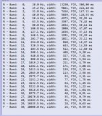
I've found a rule of thumb for tap requirements that goes 500 taps at 500Hz. Double taps for each octave decrease, halve for octave each increase
So using the 500/500 start, I get 8000 taps needed at 31Hz and only 62 taps for everything 8kHz and above !
I believe and sure as heck need to do more research, that applying linear phase is best done logarithmically.
I think an excessive linear tap count applied across all octaves might be the pre-ringing culprit. Pure speculation on my so-far observations...
Yep, i've read similar many times....it's just i don't hear it, or measure at, using 16th order.
Then that is a good thing! The only 'rules' I have come to understand govern the CHANCE of hearing detrimental effects. Room and driver variables prevent exact simple rules.
My rule of thumb is not much different to that any loudspeaker designer should adhere too whereby a smooth monotonic fall-off two octave in excess of the crossover is a very good idea. The high-pass part is generally not a problem for second order crossovers, certainly not fourth order. Generally the issues arise in the low-pass arm - and especially so in conventional two-way loudspeakers where well-behaved out-of-band driver behaviour is not common in my experience. Hence I would always advise a three-way design if you are following convention.
As far as a general threshold rule, so far I believe pre-ringing is more a function of tap count than filter order or Q.
As you point out, the higher the Q, the longer the impulse. All the 'rules' I know of relate to Q but concern non-complementary filters used in EQ sections and the like. The audibility criterion for crossovers I would suggest would be somewhat different and - as alluded to above - need to incorporate loudspeaker directivity and the room in which the measures are being made.
I believe and sure as heck need to do more research, that applying linear phase is best done logarithmically.
I don't understand this. I assume you mean logarithmically placed frequencies re minimising filter calculations? A logarithmic phase axis poses some problems...
I think an excessive linear tap count applied across all octaves might be the pre-ringing culprit. Pure speculation on my so-far observations...
I'd say that's all it is i.m.h.o, pure speculation. Or an error in the FIR file creation somewhere. There simply is no need for more pré ringing just because the tap count is higher. Something must have gone wrong in your tests here.
One can make a high tap count FIR file that covers the entire bandwidth without any pré ringing as well as one that exhibits ringing. It simply depends on what you ask it to correct and how you correct it.
Load the generated FIR filters into something like REW next time, compare them by filtering those results with IR filtering. See what happens before the zero mark.
Last edited:
I'd say that's all it is i.m.h.o, pure speculation. Or an error in the FIR file creation somewhere. There simply is no need for more pré ringing just because the tap count is higher. Something must have gone wrong in your tests here.
One can make a high tap count FIR file that covers the entire bandwidth without any pré ringing as well as one that exhibits ringing. It simply depends on what you ask it to correct and how you correct it.
Load the generated FIR filters into something like REW next time, compare them by filtering those results with IR filtering. See what happens before the zero mark.
Hi wesayso,
I think maybe your opinion comes from your experience with DRC_FIR, how it works as opposed to perhaps more simple FIR implementations.
3 things so far have led me to believe (and i do say believe 🙂... that a high tap count across the whole spectrum is bad ju-ju)
First is I hear it.
Second, one of your past posts when i was working on the line array project got me thinking. #110 https://www.diyaudio.com/forums/ful...ray-wall-corner-placement-11.html#post5805089
It appears DRC_FIR applys a frequency dependent window that effectively sets a logarithmic tap count by frequency.
I've attached a snip from that post...have I misinterpreted it?
I get the total latency will be that of a huge FIR file....it just appears DRC_FIR does the neat trick of adjusting taps employed, by frequency.
Last, at a couple of Rational Acoustic's class sessions last year, I got more familiar with the different widths of windowing necessary to make good FFT measurements.
We see that with REW too...with its 96 point-per-octave measurements..which is effectively logarithmic sampling.
So I'm like thinking...doesn't this apply logarithmic windowing equally to digital processing, just as in digital measuring...?????
Anyway, bottom line is i definitely hear some pre-echo when fir files are big across the board,... and the files seem to be too simple to have errors....
So I speculate why ...
Attachments
Last edited:
I don't understand this. I assume you mean logarithmically placed frequencies re minimising filter calculations? A logarithmic phase axis poses some problems...
Hopefully, the reply i just made to wesayso will help explain what i meant, which was a logarithmic tap count by frequency, might be best linear phase implementation without pre-ringing..
That didn't come out quite as I had intended. What I meant was that it is easy to to change the crossover frequency at will without having to completely re-engineer the whole crossover. Not that it would be easy to hear the difference in that change 🙂Big thx Fluid, ...your info helped explain well.
The only thing i would change is that i can hear different results easily.
Can't really say that.
Outdoors, when on-ax and minimized reflections, the different xover points mostly sound the same until i'm pushing the boundaries of the acceptable range.
I've chopped this quote to the bits I'm responding to.Hi wesayso,
I think maybe your opinion comes from your experience with DRC_FIR, how it works as opposed to perhaps more simple FIR implementations.
3 things so far have led me to believe (and i do say believe 🙂... that a high tap count across the whole spectrum is bad ju-ju)
First is I hear it......
It appears DRC_FIR applys a frequency dependent window that effectively sets a logarithmic tap count by frequency.
I've attached a snip from that post...have I misinterpreted it?
I get the total latency will be that of a huge FIR file....it just appears DRC_FIR does the neat trick of adjusting taps employed, by frequency......
Anyway, bottom line is i definitely hear some pre-echo when fir files are big across the board,... and the files seem to be too simple to have errors....
Far be it from me to say that you don't hear a difference but it is important to isolate that to why.
I don't believe a long filter in of itself is the cause of what you are describing.
Test it for yourself by generating a totally flat magnitude and phase filter at a ridiculous number of taps and add it in the chain at the source. If you can tell the difference (other than it taking a really long time to start after pressing play 😉 ) at that point then there is an issue and we need to work out why 🙂
DRC is not doing what you think it is. That text is the output of the frequency dependant windowing that tells you how long the window is at each of those frequencies. DRC has the ability to change those based on some parameters so it is not the straight octave band split FDW that REW does. That has nothing to do with the length of the filter that is generated at the end. This is hard to explain if you have not seen the inner workings of DRC's files. Every stage in the process can have a different length of filter applied to it too. What that windowing does is to correct a different length of the input impulse response at different frequencies.
I hope that part makes sense but I'm not surprised if it doesn't 🙂
Ultimately the final output window sets the overall length of the filter and latency. The decision on the size of that filter is based on how much frequency resolution you want to have and how much latency you can live with. The only interaction it can have with pre-ringing is that by shortening the filter you limit the amount of time in the impulse before the peak and therefore the length of time where pre-ringing can be created. The level of pre-ringing is changed by how strong you make the correction in the time domain.
The name itself is quite descriptive, it is pre-ringing or pre-echo i.e. it can only be created by changing the time/phase response of the filter before the impulse peak. If you don't change that you don't introduce pre-ringing. By making the filter acausal something has to give.
DRC can create a minimum phase version of the filter as well as linear and intermediate phase versions. If you generate a MP version it has zero pre-ringing as viewed on the impulse response regardless of the length of the filter. If you need me to make some screenshots to show you I can.
As to how much is too much that is a much harder thing to quantify. In the thread on another forum linked to before there was another link to a snare drum being processed.
The difference between minimum-phase and linear-phase EQ on transient signals such as snare drum
This is one of the clearest demonstrations of the issue I have seen, but take at a look at the filter that caused it. It is a virtual brickwall below 200 Hz with a 10dB peak of extremely high Q.
I could generate that same filter in Pro Q2 and show you the impulse resposnse, but I tell you it will be quite ugly. It is the combination of the brickwall and the high Q peak that causes that level of preringing and in a bare snare hit there is no masking from other sounds so you hear it in all it's glory 🙂 It is not the length of the filter that causes it but you could not create that type of response in a very low tap filter so in that sense only the length is a variable.
There appears to be some confusion in this thread and others concerning the audibility of pre-responses in crossover filters and pre-responses due to other linear phase filtering applications such as EQ. The latter pre-responses are intentional, the former are not and their existence emanates from a lack of complementary crossover action away from an ideal listening point..
The audibility of the 'residue' from complementary crossover filter sections not summing correctly away from the ideal listening point is dependent on a number of factors such as loudspeaker directivity (including the phase response) and room interactions: The rules of thumb regarding linear phase EQ implementations is then not likely to be of great relevance in this discussion.
The audibility of the 'residue' from complementary crossover filter sections not summing correctly away from the ideal listening point is dependent on a number of factors such as loudspeaker directivity (including the phase response) and room interactions: The rules of thumb regarding linear phase EQ implementations is then not likely to be of great relevance in this discussion.
Last edited:
The sort of pre-ringing introduced in the snare sample above could well be used as an intentional effect in music production, but it is not something that would be wanted in a playback system.There appears to be some confusion in this thread and others concerning the audibility of pre-responses in crossover filters and pre-responses due to other linear phase filtering applications such as EQ. The latter pre-responses are intentional, the former are not and their existence emanates from a lack of complementary crossover action away from an ideal listening point..
The point I was trying to make is that it does take an extreme filter to have that sort of effect.
It is also possible to end up with a cumulative effect from multiple layers of filters that are changing time responses.
I can't say I understand what you are saying in the second half of the quote.
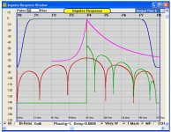
The only information I have come across in relation to thresholds of pre-ringing is attached below.
This image shows a curve in magenta before the peak where it is recommended to keep the level below to have it masked.
Attachments
The sort of pre-ringing introduced in the snare sample above could well be used as an intentional effect in music production, but it is not something that would be wanted in a playback system.
I wholeheartedly agree but in certain circumstances linear phase equalisers sound different to their minimum phase equivalents, particularly when evaluated using transient stimuli (and I have discussed in another related thread where we might identify the reasons for the increased audibility of a pre-response).
But the point I was trying to make here is that this observation is not particularly relevant to crossover filters that are the subject of this thread. What is relevant here is the audibility of the leftover (the residue) in the space where the complementary filter actions are no longer complementary. The audible consequence of this residue should cannot be ascertained by comparing it to results for evaluating inline equalisers.
It is also possible to end up with a cumulative effect from multiple layers of filters that are changing time responses.
Yes indeed, and also possible to apply phase compensation to correct them where they can be identified. The loudspeaker low frequency roll-off, the proximity effect from the stereo difference channel and even the coupling time constant in a microphone are worthy of consideration in this respect.
- Home
- Loudspeakers
- Multi-Way
- Steep Crossovers...3 steps forward, 2 steps back?