I needed to add to the above...as you will see clearly from reading GEC information about distortion, stability and power output. You should read it.
The anode is very largely insensitive to variations in the anode voltage in pentodes and beam tetrodes (because the anode is only a virtual electrode).
The main anode in those valves is the SCREEN GRID.
Variations in supply voltage on screen grids therefore make a substantial difference to the internal gain of the valve, and a very substantial contribution to distortion or lack of it. (GEC states this).
Therefore their recommendation is no more than a 5% variation in screen voltage in order to meet the requirements of distortion and power output.
Typical screen voltages being +/- 2.5% (total 5%) means in effect at 300V no higher than 307, and no lower than 293.
Very very few amplifiers observe this golden rule.
Being as the vast majority of screen supplies are obtained thru dropping resistors, it makes a nonsense of linearity even when it has a fully aligned screen, and even worse when using the "ultra linear connection taps".
(I always measure screen current and voltages under full load & at all frequencies not the dumb industry standard of 1khz / 1watt. They can be very revealing).
For this reason alone why I always make a voltage stabiliser for the screen and negative bias lines, and never use UL connections, because it causes dynamic compression.
Therefore it does shows:-
The good sound of an amp is not dictated by the size of your wallet, but technical competence, always has been.
This is especially as regards to output valve screen grid stabilisation and lack of compression loading on the -ve bias line (as Tronola has amply proved for years and years now).
In fact I would go so far as to say those guys Lafferty & Gillespie, have done more for the understanding of optimisation and improvement of push pull amps than any of the contributions on this forum,-
as well as going to great trouble to measure differences in power output of NOS OEM components versus modern REPRO stuff.
The anode is very largely insensitive to variations in the anode voltage in pentodes and beam tetrodes (because the anode is only a virtual electrode).
The main anode in those valves is the SCREEN GRID.
Variations in supply voltage on screen grids therefore make a substantial difference to the internal gain of the valve, and a very substantial contribution to distortion or lack of it. (GEC states this).
Therefore their recommendation is no more than a 5% variation in screen voltage in order to meet the requirements of distortion and power output.
Typical screen voltages being +/- 2.5% (total 5%) means in effect at 300V no higher than 307, and no lower than 293.
Very very few amplifiers observe this golden rule.
Being as the vast majority of screen supplies are obtained thru dropping resistors, it makes a nonsense of linearity even when it has a fully aligned screen, and even worse when using the "ultra linear connection taps".
(I always measure screen current and voltages under full load & at all frequencies not the dumb industry standard of 1khz / 1watt. They can be very revealing).
For this reason alone why I always make a voltage stabiliser for the screen and negative bias lines, and never use UL connections, because it causes dynamic compression.
Therefore it does shows:-
is pretty much a nonsense.The PS transformers are each 572VA.
large difference on your wallet, and your chassis real-estate.
The good sound of an amp is not dictated by the size of your wallet, but technical competence, always has been.
This is especially as regards to output valve screen grid stabilisation and lack of compression loading on the -ve bias line (as Tronola has amply proved for years and years now).
In fact I would go so far as to say those guys Lafferty & Gillespie, have done more for the understanding of optimisation and improvement of push pull amps than any of the contributions on this forum,-
as well as going to great trouble to measure differences in power output of NOS OEM components versus modern REPRO stuff.
For this reason alone why I always make a voltage stabiliser for the screen and negative bias lines, and never use UL connections, because it causes dynamic compression.
never like ultralinears myself, regulated G2 using mosfet pass and zener are what i use..
Your "speed" obviously requires copies amounts of LSD to make it happen.
My own amplifier gives perfectly linear response down to 8Hz and literally apartment shaking bass,which your woofers obviously are incapable of.
The amplifier is a modified industrial valve unit.
You can't make generalisations about anything if you are doing it all wrong in the first place.
i am relating an anecdote, my own experience, you can not judge anything since you were not there....we were...
Last edited:
i am relating an anecdote, my own experience, .
yes and I am relating the fact that these junk terminologies such as
or slam or all the other nonsense terms are actuallyif you want "speed"
JUNK.
Junk in = junk out.
The good sound of an amp is not dictated by the size of your wallet, but technical competence, always has been.
This is especially as regards to output valve screen grid stabilisation and lack of compression loading on the -ve bias line (as Tronola has amply proved for years and years now).
.
You get what you pay for - that was that was meant. Regulated supplies cost money. So do larger transformers. Technical competence would say it needs to be the unloaded DC times the peak instantaneous draw divided by the power factor, to keep it from sagging. But that’s harder on your wallet than the ones third to one half of that needed to just barely meet the temperature rise spec. Zener diodes and hexfets and the heat sink to go on it may not cost much to you, because you probably have 40 left out of 50 of them sitting in a drawer you bought 5 or 10 years ago. that’s a hidden cost that a manufacturer or a newbie building from the ground up won’t ignore.
Regulation, regulation, regulation
Here I sit on a cold Saturday, reading yet again about rectifryers. (sic)
And at the end, taking “properly designed” around post № 2, taking “shouldn't change” around post № 5, and “save the vacuum rectifiers for a museum” somewhat past that, I'm left with one “string” that best fits:
That's my real point. Regulation Accomplishes that handily, and these days, incurring neither complexity nor high cost.
It is truly amazing what one can accomplish with a few Zeners and MOSFET 'source follower' style series regulators in the PSU. 2 (optimal) or 3 (max…) stages squashes all audible PS hum, yet still keeps downright impressive current-sourcing capacity in a PSU for the amplifier's finals to eagerly slurp up.
Anyway,
⋅-⋅-⋅ Just saying, ⋅-⋅-⋅
⋅-=≡ GoatGuy ✓ ≡=-⋅
Here I sit on a cold Saturday, reading yet again about rectifryers. (sic)
And at the end, taking “properly designed” around post № 2, taking “shouldn't change” around post № 5, and “save the vacuum rectifiers for a museum” somewhat past that, I'm left with one “string” that best fits:
regulation, regulation, regulation, regulation, regulation!
IF (the OP's opening salvo!) a “properly designed” power supply is … a (( transformer → rectifier → capacitor-and-various-ripple-mitigating-network → B+ supply! )), then one really ought to embrace a design that also mitigates for device ageing and source variation, right?That's my real point. Regulation Accomplishes that handily, and these days, incurring neither complexity nor high cost.
It is truly amazing what one can accomplish with a few Zeners and MOSFET 'source follower' style series regulators in the PSU. 2 (optimal) or 3 (max…) stages squashes all audible PS hum, yet still keeps downright impressive current-sourcing capacity in a PSU for the amplifier's finals to eagerly slurp up.
Anyway,
⋅-⋅-⋅ Just saying, ⋅-⋅-⋅
⋅-=≡ GoatGuy ✓ ≡=-⋅
It is truly amazing what one can accomplish with a few Zeners and MOSFET 'source follower' style series regulators in the PSU.
It's truly amazing what you can accomplish with 2 x SG5b 150V gas tubes, and a cathode follower.
2 lines,- one high current the other shunt regulated low current.
Even easier than Mosfets, and gives you TWO stable hum free lines not just ONE. 🙄
I hope not. I mean, there is much mentioned here about the supply being set up right. All considered, you can't just swap rectifiers and expect a fair result.
The SET I am building was designed to be switchable between SS and tube rectification. Yes, the B+ (and hence the bias voltage) will be higher with SS rectification but that was taken into consideration by the designer (AFAIK). The builder has to choose an appropriate cathode-bias resistor value so that the possible combinations of power tubes and rectification are within the operating specs of the power tubes. A 5AR4 is recommended in the amp, which I have learned has a fairly low voltage drop compared to some others. It is possible to use 5U4 and 5R4 as well (as long as the 5v winding can handle the extra current, which mine will). These will drop the B+ even more. It might sound like crap, but I am going to try them anyway. I want to hear the results of all these changes. I want to understand it.
The power supply will be C-L-C with a large auxiliary motor-run cap. I don't think it will be a limiting factor for the desired power/SPL.
Last edited:
Here I sit on a cold Saturday, reading yet again about rectifryers. (sic)
And at the end, taking “properly designed” around post № 2, taking “shouldn't change” around post № 5, and “save the vacuum rectifiers for a museum” somewhat past that, I'm left with one “string” that best fits:regulation, regulation, regulation, regulation, regulation!IF (the OP's opening salvo!) a “properly designed” power supply is … a (( transformer → rectifier → capacitor-and-various-ripple-mitigating-network → B+ supply! )), then one really ought to embrace a design that also mitigates for device ageing and source variation, right?
That's my real point. Regulation Accomplishes that handily, and these days, incurring neither complexity nor high cost.
It is truly amazing what one can accomplish with a few Zeners and MOSFET 'source follower' style series regulators in the PSU. 2 (optimal) or 3 (max…) stages squashes all audible PS hum, yet still keeps downright impressive current-sourcing capacity in a PSU for the amplifier's finals to eagerly slurp up.
Anyway,
⋅-⋅-⋅ Just saying, ⋅-⋅-⋅
⋅-=≡ GoatGuy ✓ ≡=-⋅
Or brute force it like I do? 😀
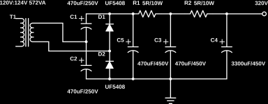
This simple supply powers my amps (PP output stage only, other amp stages and bias supply are DC boost converters powered from the heater supply). I have a feeling if I replaced the UF5408 with 6D22S, they would explode haha!
320V with a 400mA load dropping to 305V with 1A or so. There isn't enough voltage overhead for a 300V regulator I've been told.
BTW the monoblocs 112W output was tested using sine wave drive, just before clipping, 30Hz, 6R load for an effective 1k Ra-a, 4 6P45S tubes trioded for PPP operation. It will do this all day happily.
Attachments
Last edited:
The SET I am building was designed to be switchable between SS and tube rectification. Yes, the B+ (and hence the bias voltage) will be higher with SS rectification but that was taken into consideration by the designer (AFAIK). The builder has to choose an appropriate cathode-bias resistor value so that the possible combinations of power tubes and rectification are within the operating specs of the power tubes. A 5AR4 is recommended in the amp, which I have learned has a fairly low voltage drop compared to some others. It is possible to use 5U4 and 5R4 as well (as long as the 5v winding can handle the extra current, which mine will). These will drop the B+ even more. It might sound like crap, but I am going to try them anyway. I want to hear the results of all these changes. I want to understand it.
The power supply will be C-L-C with a large auxiliary motor-run cap. I don't think it will be a limiting factor for the desired power/SPL.
You can also try 5Y3GT for extra sag 😀
You can also try 5Y3GT for extra sag 😀
We already established that sag isn't a factor in a class A SET, so swapping rectifiers will only change voltage drop (yes I know there are other factors such as directly or indirectly heated...), which will change B+, which will change various operating conditions of the power tubes (including bias in a cathode-bias setup). As long as these operating conditions are within the power-tube specs, it'll work. Simulations indicate that the corresponding changes in dissipation, output power, distortion, etc. are actually quite small when B+ shifts by 20 or 30 volts. As I stated before, selection of the cathode-bias resistor value is key. It needs to be a value that results in a "happy medium" so that various rectifiers don't take the power tubes too far out of spec.
This is the way I understand it so far, but most of you around here have forgotten more than I have learned about it and I would be glad to know/understand more. Just don't convince me I am building a bad design, because I already have quite a lot of money into it. 🙂
Yup. My bad. I only build PP amps so far...
Bottom line is any rectifier will do the job, but using SS wastes less power, and allows the use of giant caps to get rid of ripple without losing a lot of voltage.
Bottom line is any rectifier will do the job, but using SS wastes less power, and allows the use of giant caps to get rid of ripple without losing a lot of voltage.
Or brute force it like I do? 😀 I… will do this all day happily.
So, yah. Here's my design response to that (very good) schematic:
⋅-⋅-⋅ Just saying, ⋅-⋅-⋅
⋅-=≡ GoatGuy ✓ ≡=-⋅
Attachments
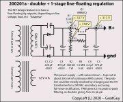
As noted, just using a 240 VAC secondary über-cheap transformer and a full-wave bridge cures that, straight up, without the half-wave doubler, and its inbetween peaks. No values changes needed.Nice, but the amp idles at 400mA and peaks over 1A! Still, pretty simple 🙂
One might also consider adding one of your HF filtering sections before the MOSFET … what was it, a 10 Ω / 10 W resistor and another 470 µF reservoir cap.
OR, if you have the space, a 0.25 to 0.5 H inductor of sufficiently low RDC. That would be better, as it really soaks up the HF crud.
This configuration (FWB, REG) is what I've generally been designing in to anything HiFi'ish.
When designing for guitar amps, all that theory is tossed out, and we're actually hoping for squirrelly PSU crud!
⋅-=≡ GoatGuy ✓ ≡=-⋅
Good to know. The transformers I'm using right now are 62-0-62@2.5A DC (572VA) so I'm just leaving the CT disconnected and using the Delon. If I was to buy a transformer though, it'd probably have dual 115V secondaries for series 230V operation.
Good to know. The transformers I'm using right now are 62–0–62@2.5A DC (572VA) so I'm just leaving the CT disconnected and using the Delon (Bridge). If I was to buy a transformer though, it'd probably have dual 115V secondaries for series 230V operation.
I see. Odd transformer. Also, I take “it back” … apparently the Delon Bridge is a pseudo-full-wave configuration. Who knew? The positive going cycles definitely have a 16.7 ms gap, and the negs, too. But they're offset from each other by 8.3 ms, so the effective ripple is reduced therein.
I'm going to have to toss together one of these and look at it on the oscilloscope. Just a 12 volt one, of course. So I can touch bare wires with my hot fingers, while standing in a puddle with stocking'd feet . .. … LOL.
Ya, they were surplus and only cost me 20$CAD a piece 🙂 I have only three though.
Let me know what you think of it. Large caps in the "bridge" help with ripple, too. You knew that though.
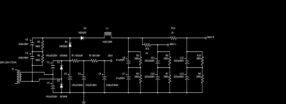
Here's a more complex one with a half wave quadrupler on top of it for the front end of the amp if I don't use the DC boards. I think Mona helped me with this.
Let me know what you think of it. Large caps in the "bridge" help with ripple, too. You knew that though.
Here's a more complex one with a half wave quadrupler on top of it for the front end of the amp if I don't use the DC boards. I think Mona helped me with this.
Attachments
Last edited:
yes and I am relating the fact that these junk terminologies such as or slam or all the other nonsense terms are actually
JUNK.
Junk in = junk out.
there are no forum rules against stupid, that word did not come from me, i merely reacted to it, read again and find out who said it...never was my idea...
read post #1 again, it was mentioned there first since it was the first post, it is that post that you should react to...
Last edited:
there are no forum rules against stupid, that word did not come from me, i merely reacted to it, read again and find out who said it...never was my idea...
read post #1 again, it was mentioned there first since it was the first post, it is that post that you should react to...
Except that I never used the word "slam", I used the word "speed" and used quotes (as I did here) because I already understand how ridiculous it is. In a way, it is simply descriptive of the way a PS reacts to power demand. Does it simply provide the demanded power, or does it "sag" because it can't keep up? One could say the "sagless" PS is "stiffer" (I've seen it used plenty) or they could say "faster", or any number of other words. They are just words used to try to convey some semblance of what the PS is doing under heavy loads or peaks.
Last edited:
neither did i.....words like speed, slam, they are words that i can tolerate and not have a reaction unless someone made a big deal of this non-issue...
to each his own....
sag is the unavoidable as a consequence of dc resistances along the way of the current going into the load...
if you want your load voltage not to sag, then voltage regulators of sufficient compliance can be used...
or better yet, an smps psu can be used...
to each his own....
sag is the unavoidable as a consequence of dc resistances along the way of the current going into the load...
if you want your load voltage not to sag, then voltage regulators of sufficient compliance can be used...
or better yet, an smps psu can be used...
Last edited:
- Home
- Amplifiers
- Tubes / Valves
- Rectifier "Sound"?