Hi Horika,
I was able to get my rpi with ians fifopi running.. had to reflash and it worked.
Thanks
I was able to get my rpi with ians fifopi running.. had to reflash and it worked.
Thanks
Hi Ben,
Lately, when soldering pads with a high thermal mass ive been preheating the board with hot air before soldering with an iron - makes it so much easier, the solder flows and wets into all areas with ease.
Ryan,
I like that method. You might post some of these as tips......just saying 😀
Hi Greg,
To clarify I am working under magnification and I am not preheating my boards, but I do use a fair amount of no clean flux a Hakko 888 iron with a .8mm tip at 650F and .015in diameter 63/37 Kester. I first put down some flux then add some solder to the first pad on the board of the item I am intending to solder. I then solder the item down to that first fluxed/soldered pad. Then finish the rest on the item, working fast so as not heat anything up too much. Having the really small solder wire helped me tremendously.
This method has worked for 2 simultaneous boards and 2 D3 boards and I have never done SMD soldering before this project.
Good luck,
Mark K.
Not sure If I have many more tricks up my sleeve. 😛
Ryan,
I like that method. You might post some of these as tips......just saying 😀
Hi Guys,
What is the output impedance after the iv resistor? Say im using 150 ohm iv resistor? Is the output impedance 150 ohms as well?
Thanks
What is the output impedance after the iv resistor? Say im using 150 ohm iv resistor? Is the output impedance 150 ohms as well?
Thanks
Hi, if i use two d3 panels in simultaneous mode driven by ryan logic converter what is the correct aor connection? would someone put a block sketch here?
I use an I / V resistor. a transformer test is also planned.
I use an I / V resistor. a transformer test is also planned.
Hi, if i use two d3 panels in simultaneous mode driven by ryan logic converter what is the correct aor connection? would someone put a block sketch here?
I use an I / V resistor. a transformer test is also planned.
Hi horika,
If running in parallel with 2 boards it would be best to use one 1541 chip per channel, and use just the one IV resistor per channel.
Yes that is right. but should I put the I / V resistance between 25 pins and 6 pins?
No, pin 25 and 6 need to have a path to ground.
then 25 in and 6 pin connect and common point and body between I / V resistance? or an I / V resistor between 25 pins and gtest and a resistor between 6 pins and gtest. output 25 pins and 6 pins? sorry to ask but so i have not used tda chips in this mode
Last edited:
then 25 in and 6 pin connect and common point and body between I / V resistance? or an I / V resistor between 25 pins and gtest and a resistor between 6 pins and gtest. output 25 pins and 6 pins? sorry to ask but so i have not used tda chips in this mode
Populate R36 and R35 with your IV resistor, then AOL1 and AOR1 are your outputs, adjust TR1 and TR2 until you get 0V on AOL1 and AOR1, if running in parallel then you connect AOL1 and AOR1 together.
Hi, if i use two d3 panels in simultaneous mode driven by ryan logic converter what is the correct aor connection? would someone put a block sketch here?
I use an I / V resistor. a transformer test is also planned.
I just saw you PM to me - Are you planning on operating in parallel or differential? If running in differential mode you will need to invert the data lines, have you done this?
1st D3 needs:
LE, BCK, RIGHT DATA, INVERTED RIGHT DATA
2nd D3 needs:
LE, BCK, LEFT DATA, INVERTED LEFT DATA
Last edited:
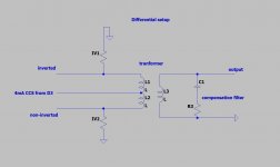
Differential example
Horika,
Attached is an example of how to configure your DAC if you are using a transformer with a differential output. It seems to work very well in my setup.
The inverted and non-inverted in the example should be swapped around.
Horika,
Attached is an example of how to configure your DAC if you are using a transformer with a differential output. It seems to work very well in my setup.
The inverted and non-inverted in the example should be swapped around.
Attachments
Last edited:
A thought hit me, yes it did hurt....
Has anyone tried using Muse BP across the 22uF acrylic capacitors?
Same value, higher value doesn't matter I'm wondering if anyone has tried it and the results of that test.
How critical is the tolerance of the 10R 2W resistor.
I seem to have misplaced mine. Closest I got with two THT 1W resistors was 10.8R. So I left that spot unpopulated for now.
I made a layout for the BF862 I/V floating around the web. It works in simulation at least.
Then there's the DDNF I built with boutique parts.
I've considered doing a layout of that circuit using SMD's, only for my own personal use as I have not asked the designer for permission to share nor do I want the hassle of sending out boards.
Ryan,
I just started populating my second board, and I just populated exactly what you told me to and all my voltages are very close, but a bit low, with no load. ~4.89, -4.9 and -14.9. Should I proceed? I don't have a load set up.
Cheers,
Greg
I just started populating my second board, and I just populated exactly what you told me to and all my voltages are very close, but a bit low, with no load. ~4.89, -4.9 and -14.9. Should I proceed? I don't have a load set up.
Cheers,
Greg
Horika,
Attached is an example of how to configure your DAC if you are using a transformer with a differential output. It seems to work very well in my setup.
The inverted and non-inverted in the example should be swapped around.
Thanks. I ended up. It works. I use it in differential mode. 100% made with recommended parts. Unfortunately, the jack voltage (50Hz) sits on the hand. I'm looking for the bug but can't find it. idea?
A thought hit me, yes it did hurt....
How critical is the tolerance of the 10R 2W resistor.
I seem to have misplaced mine. Closest I got with two THT 1W resistors was 10.8R. So I left that spot unpopulated for now.
Hi Mayday,
10.8R should be ok, you will get a lower current resulting in higher z-out at the supply voltages but it may not be noticeable.
Ryan,
I just started populating my second board, and I just populated exactly what you told me to and all my voltages are very close, but a bit low, with no load. ~4.89, -4.9 and -14.9. Should I proceed? I don't have a load set up.
Cheers,
Greg
Hi Greg,
Those voltages are good, once you put all the caps in place the voltages will come up to spec.
Thanks. I ended up. It works. I use it in differential mode. 100% made with recommended parts. Unfortunately, the jack voltage (50Hz) sits on the hand. I'm looking for the bug but can't find it. idea?
Hi horika,
Attach the GND on the secondary to the DAC GND. Seemed to get rid of the 50hz noise for me.
Hi Mayday,
10.8R should be ok, you will get a lower current resulting in higher z-out at the supply voltages but it may not be noticeable.
So, a slightly lower value, if I can find among my 1W THT resistors (used in parallel) would be preferable?
Say with the same error margin, that would make it 9.2R.
Would that set the current too high?
I'll try my best to either locate the missing 10R or find something a lot closer to 10R.
- Home
- Group Buys
- DIY TDA1541A PCB "D3"