@X I don't see a leak, I just see a whole lot of air in those hoses, never seen that much air in any I have used, though I've only used a couple like that.
CPU coolers with heat pipes never leak and don’t require water changes. It’s fun to play with water cooling but might be messy. Also, that copper block will only hold one MOSFET. Make sure the pump in that copper block is not too noisy.
The radiator can be saved but maybe you might need a new pump/copper block.
I have decided I am going to use these CPU air coolers for each MOSFET - so 4 for a dual mono case:
Cooler Master GeminII M5 LED Low-Profile CPU Air Cooler - RR-T520-16PK | Mwave.com.au
So no heatsinks on the case - merely 4 of these CPU coolers inside. Each can take 130w.
This means a big floor area - so I am going to use this Modushop case (no heatsinks):
Pesante 03P400N 3U 10mm NERO
Fans will be controlled for speed - haven't quite figured out the details. 🙁
Andy
@Andy
You going to make some sort of sink transfer spacer to make sure you spread the heat over all the pipes? Hard to tell by looking, but it looks like one may be needed to ensure even distribution to the pipes. When you get you mind around it let us know the details... I'm looking at one of these type as well.
You going to make some sort of sink transfer spacer to make sure you spread the heat over all the pipes? Hard to tell by looking, but it looks like one may be needed to ensure even distribution to the pipes. When you get you mind around it let us know the details... I'm looking at one of these type as well.
You need a rack mount computer server case that has air vents front and back and fans pushing air through. Or your case will have ventilated too and bottom panels? Of no top? In any case, having a CPU cooler extract the heat to air trapped inside a case with poor ventilation is not going to work. If you do that, you need to use Noctua fans all around or the fan noise will drive you nuts. Just think of how much ventilation a computer case normally has for just one or two CPU coolers. Now you have 4 of them.
The Alpha Nirvana was designed to have a heat load sustainable with a standard 4U or 5U passive fin heatsink.
Another way is to have them extend through cutouts on the top panel and exposed to room air. Then the fans can work without a second fan to move air through the case.
The Alpha Nirvana was designed to have a heat load sustainable with a standard 4U or 5U passive fin heatsink.
Another way is to have them extend through cutouts on the top panel and exposed to room air. Then the fans can work without a second fan to move air through the case.
@Andy
You going to make some sort of sink transfer spacer to make sure you spread the heat over all the pipes? Hard to tell by looking, but it looks like one may be needed to ensure even distribution to the pipes. When you get you mind around it let us know the details... I'm looking at one of these type as well.
Not quite sure why you think a 'sink transfer spacer' is needed, TT? 😕
Shirley, if the o/p MOSFET is squeezed against that pad which has the copper tubes through it (by bolting this pad to the base of the case), then MOSFET heat will get transferred into the CPU air cooler pad?
You need a rack mount computer server case that has air vents front and back and fans pushing air through. Or your case will have ventilated too and bottom panels?
Yes, Modushop offer fully ventilated top and bottom panels for their Pesante cases
The Alpha Nirvana was designed to have a heat load sustainable with a standard 4U or 5U passive fin heatsink.
But I don't want a 4RU or 5RU case! 🙂 IMO, solving the heat issue by having large heatsinks is the brute-force-but-ugly approach ... whereas using these CPU coolers is the high-tech-and-elegant approach! 🙂
Fan noise is a potential problem but this particular CPU cooler:
* seems to offer lower fan noise levels than others I looked at, and
* the fan speeds can be PWM controlled. As they're 12v fans, this should mean I can use a domestic dimmer used for 12v LED lights (which are also PWM controlled).
Andy
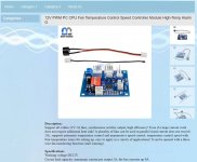
You just get one of these PWM fan controllers. They have variable speed and alarm setpoints and temp thermistor.
12V PWM PC CPU Fan Temperature Control Speed Controller Module High-Temp Alarm G | eBay
Each will run 2-3 fans. Needs 12v input.
They have standard PWM CPU fan connectors. You need to read the instructions on setting the dip switches. But these are amazingly cheap and work well.
12V PWM PC CPU Fan Temperature Control Speed Controller Module High-Temp Alarm G | eBay
Each will run 2-3 fans. Needs 12v input.
They have standard PWM CPU fan connectors. You need to read the instructions on setting the dip switches. But these are amazingly cheap and work well.
I have decided I am going to use these CPU air coolers for each MOSFET - so 4 for a dual mono case:
Cooler Master GeminII M5 LED Low-Profile CPU Air Cooler - RR-T520-16PK | Mwave.com.au
So no heatsinks on the case - merely 4 of these CPU coolers inside. Each can take 130w.
This means a big floor area - so I am going to use this Modushop case (no heatsinks):
Pesante 03P400N 3U 10mm NERO
Fans will be controlled for speed - haven't quite figured out the details. 🙁
Andy
Hi Andy,
4 cpu coolers, fan controllers, 2 trafo’s, 2 SLB’s, 2 AN boards and enough room at the rear panel for inputs/outputs/protection and AC input module is a lot to shoehorn into 430mm x 400mm x 120mm of interior space. Maybe a pair of Pesante’s, a bit smaller, for monoblocks 🙂
Hi Andy,
4 cpu coolers, fan controllers, 2 trafo’s, 2 SLB’s, 2 AN boards and enough room at the rear panel for inputs/outputs/protection and AC input module is a lot to shoehorn into 430mm x 400mm x 120mm of interior space. Maybe a pair of Pesante’s, a bit smaller, for monoblocks 🙂
Yes, that's very true, Vunce! 🙂
But I've drawn it out on paper (taping together a couple of A3 sheets to get the 400mm deep x 430mm wide space) ... and it all just fits! SLBs are mounted sideways, though - as is the 12v SMPS for the fans.
Andy
Well done Andy!
I’ll be looking forward to your building progress 😉
Thanks, Vunce.
I can tell you it's going to be slow! 😀
But I plan to post pics, along the way.
Andy
You just get one of these PWM fan controllers. They have variable speed and alarm setpoints and temp thermistor.
12V PWM PC CPU Fan Temperature Control Speed Controller Module High-Temp Alarm G | eBay
Each will run 2-3 fans. Needs 12v input.
They have standard PWM CPU fan connectors. You need to read the instructions on setting the dip switches. But these are amazingly cheap and work well.
That's very cool, X! 🙂
Spec says it can output 5a - so 4 fans sucking a total of 750ma will be no problem at all.
Looking at the attached pic (taken from the eBay ad), I take it that the black round thing at the top left (attached to the red/black wires) is the knob which you turn to change fan speed?
Andy
Attachments
Looking at the attached pic (taken from the eBay ad), I take it that the black round thing at the top left (attached to the red/black wires) is the knob which you turn to change fan speed?
Andy
Actually, the “knob” is a buzzer for the alarm 😀
The other is the temp sensor, you can sandwich the tip into the cpu cooler fins.
The fan speed and settings are controlled by the dip switches.
Feed this control board 12vdc and your good to go!!
I also have an order in for an Antek AN-6224 600VA 24v trafo to make circa 27v to 29v under load for both chanel
I have a couple of PSU questions and shall appreciate some input. I wondered if for my situation (explained below) a 22v transformer would be acceptable, if not preferable. Hugh’s design called for +/- 27 vdc. Based on X’s build and use of SLB PSU I believe he gets 28.5 vdc in practice.
Question 1: X, for the record, what is your wall power AC voltage? Mine is consistently 125-128 VAC. So, if X’s utility provides around 125Vac, I estimate that I should get about +/- 26 vdc from a 22 vac transformer also using a SLB PSU.
Question 2: Is a supply of +/- 26 vdc acceptable for the AN, or is +/- 28.5 vdc preferable? I do not mind loosing a few watts output power, and will appreciate reducing the heatsink load a bit.
Question 3: Will a 500VA transformer be sufficient for my two channel build? Unfortunately Antek does not offer a 22 VAC transformer in VA rating >500 (AN-5222). Or should I just get the AN-6424 even though I might end up with a supply of +/-29 or so?
Your discussion and input shall be appreciated.
Last edited:
Actually, the “knob” is a buzzer for the alarm 😀
Oh! 😱
The other is the temp sensor, you can sandwich the tip into the cpu cooler fins.
Yes, that would be great.
The fan speed and settings are controlled by the dip switches.
Then this ain't gonna work! 🙁
If it's a hot summers day when I'm sitting down to listen - I'll need the fans on max.
On other days, I'm hoping I can reduce their speed ... and their noise. I don't want to have to unscew the lid, in order to make these changes.
But then again - this is all conjecture, at this stage. It may be the fans at max are quiet enough. 🙂
Andy
Last edited:
The fan speed is adjusted automatically by the relationship between the temp sensor and how the dip switches are set. Once you have the settings acceptable, you don’t need to touch again 🙂
Go with Noctua PWM fans!! They are silent, I’ve left my amps on overnight accidentally because they are so quiet.
Go with Noctua PWM fans!! They are silent, I’ve left my amps on overnight accidentally because they are so quiet.
Andy,
The speed is also set by the two little trim pots on the board. The DIP switch sets the threshold behavior and the PCB pots set the max speed.

The speed is also set by the two little trim pots on the board. The DIP switch sets the threshold behavior and the PCB pots set the max speed.
Features:
100% High quality and Brand new
Support all within 12V 5A fans, synchronous rectifier output, high efficiency! Even if a large current work does not require additional heat sink! A plurality of fans can be used in parallel (total current does not exceed 5A), supports automatic temperature control and manumotive speed control, temperature control speed with four temperature zones for setting up, easy to apply in a variety of applications! It can be opened with a three-wire fan monitoring function (stall warning).
Working voltage😀C12V
Circuit load capacity: maximum current per output 5A, the bus currents up 9A
Output Range: The first channel 20% -100%, or 40% -100% (TFL = ON)
The second channel and the third channel 10% -100%
(Note: Above range only for PWM range, the actual control effect will vary depending on the fan.)
Temperature probe parameters: 50K B = 3950
Thermostat temperature zone error: error depending on the temperature probe, generally 3-5%
Stall alarm minimum speed: 700-800 rpm
Function setting switch Description:
TFL (No. 1): The lowest temperature channel PWM setting, when ON state FAN1 PWM minimum is 40%, when OFF the minimum PWM of FAN1 is 20%.
TP1 TP2 (No. 2,3): Temperature channel control temperature zones are interpreted as follows (need to used with the temperature probe):
TP1 TP2 Accelerating temperature Full speed temperature
OFF OFF 35° 45°
ON OFF 40° 55°
OFF ON 50° 70°
ON ON 60° 90°
When the temperature lower than the accelerated temperature, then output at the minimum rotation speed; when it exceed over the full temperature, then always output at full speed.
BF1 BF2 (No. 4,5): corresponds FAN1 FAN2 stall alarm function switch, when the corresponding open channel fan break down, the controller will alarm with soundand light (works with buzzle), alarm will automatically eliminated when the fan is rotated recovery . If BF1 and BF2 both are open (ON), the FAN1, FAN2 have any one or both stops, the controller will alarm!
I have a couple of PSU questions and shall appreciate some input. I wondered if for my situation (explained below) a 22v transformer would be acceptable, if not preferable. Hugh’s design called for +/- 27 vdc. Based on X’s build and use of SLB PSU I believe he gets 28.5 vdc in practice.
Question 1: X, for the record, what is your wall power AC voltage? Mine is consistently 125-128 VAC. So, if X’s utility provides around 125Vac, I estimate that I should get about +/- 26 vdc from a 22 vac transformer also using a SLB PSU.
Question 2: Is a supply of +/- 26 vdc acceptable for the AN, or is +/- 28.5 vdc preferable? I do not mind loosing a few watts output power, and will appreciate reducing the heatsink load a bit.
Question 3: Will a 500VA transformer be sufficient for my two channel build? Unfortunately Antek does not offer a 22 VAC transformer in VA rating >500 (AN-5222). Or should I just get the AN-6424 even though I might end up with a supply of +/-29 or so?
Your discussion and input shall be appreciated.
My mains is 118 to 122VAC but highly non sinusoidal - ugly looking “bread loaf” shape - hence generates lots of harmonics from rectification. With Antek I would always go with the “next one up” as they seem to be consistently over-rated (they sag by 3-5v) under larger Class A loads.
- Home
- Amplifiers
- Solid State
- Alpha Nirvana 39w 8ohm Class A Amp