You can get a 5dB bump by splitting the base stopper and making the slow-start cap do double-duty as a filter:

So I ran some tests with the various Jam Jar incarnations to see if this was worth incorporating.
Pffft.
The 'CFA' front end is the hardest on the regulator of the three. Its distortion measurements start to be impacted when the regulator's Zout falls below about 100mOhm.
The above fix reduces Zout from 3mOhm to 2.5. Where's Jam's "Yeah Nah" coffee mug?
Attachments
People with access to university libraries full of hardcover books, or to simulation programs like HSPICE which include the ".OPTIMIZE" command/directive,
can potentially do the same thing using passive filters. They can achieve the minimalist nirvana of "no additional active components". Luckily, in this application the inductors carry zero DC current and less than 100uA signal current. So you don't have to worry about series resistance or saturation limits when choosing inductors.
I owned a first generation Sony CDP-101 CD player, whose 22 kHz antialising filter was implemented as a minimalist passive filter using inductors, capacitors, and resistors but no active components. It was so wonderful and so optimum that Sony never did it again, ever, in any of their subsequent CD players. I guess they decided that opamps are cheaper than precision inductors.
Opamp output with 220dB less noise than a zener?
What is the noise of that zener?
A couple of weeks ago I spent a day struggling with the error tolerance parameters in SPICE trying to get it to show me below 4.6mV ripple from my previous regulator.
Turned out not to be the error tolerance of SPICE -- it was the background noise of the opamp. 😎
But he only goes up to the cross-over region, no? Christer's work would suggest it starts going back down again not long after that.
Jeff,
the only other thing I found that Gerhard said about his tests was this here.
Zeners have a bad reputation as being noisy. That is not the case for small voltages where they work as true Zeners. Only above 5V where the avalanche effect sets in, noise gets out of hand. Note the low 1/f corner of the BZX84.
"Shorted" means that the input of the amplifier is shorted to ground. That is the amplifier's own voltage noise.
Z1 / Z14 / Z5p etc is the marking on the chip, so I can find them easier on the table. The actual Zener voltage is slightly larger than nominal because of the generous bias current.
Yeah, Microsemi diodes give the following measurements at Izt
4.7V Zeners have 1uv/(Hz)^0.5 of noise
Zeners at 6.8V and above measure 40uV/(Hz)^0.5
A 40 fold increase in noise going from 4.7V to 6.8V and above.
The temperature coefficient is also good at 4.7V compared with high voltage zeners.
https://www.microsemi.com/document-portal/doc_download/129734-lds-0245-2-datasheet
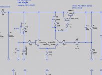
Borbely's all-FET regulator uses a current source instead of a current mirror inside the LTP. I tried it out, and it performs about the same, although it has better margins leaving room to experiment with different transistors.
Mostly just curious to see what people think about it....

Mostly just curious to see what people think about it....
Attachments
A bit of discussion on practical choice on jfets for current sources.... Mostly just curious to see what people think about it...
Ideally you would like to use a high input impedance jfet for a constant current source, so a 2SK246 is prefered over the 2SK170. It is, however, a large pinch-off voltage jfet, so voltage drop is larger...
http://liveweb.archive.org/http://www.vishay.com/docs/70596/70596.pdf
those intersted will probably want all of the Siliconix app notes: JFETs Application notes
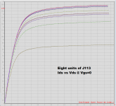
I always got better curve tracer measured performance using BJTs for current sources, at least in applications where the current source must operate with a small end-to-end voltage. For example, the JFET circuit plotted in Figure 2 below (using J113), doesn't really flatten out until you apply ~3.5 volts across it. But your voltage regulator application attempts to operate this current source with only 2 x VBE across it. That's only 1.3 volts. How good or how bad a current source is Figure 2 below, at 1.3 volts? P.U. Pew.
In my experience, to get a single-transistor current source with acceptably high dI/dV {for good gain}, you need
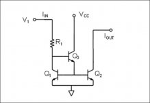
Another way to skin the cat, of course, is to build a cascode out of two BJTs. If you carefully arrange to operate each transistor at VCE = 0.6 * VBE, you can get a truly excellent current source with truly excellent performance at low end-to-end voltage. But it costs another transistor.
_
In my experience, to get a single-transistor current source with acceptably high dI/dV {for good gain}, you need
- A BJT with excellent quasi-saturation behavior (i.e. NONE) at VCE = 0.5V ... which also exhibits
- Very high Early voltage (>200 volts measured) ... and if possible
- High Beta (>200 amps per amp)
Another way to skin the cat, of course, is to build a cascode out of two BJTs. If you carefully arrange to operate each transistor at VCE = 0.6 * VBE, you can get a truly excellent current source with truly excellent performance at low end-to-end voltage. But it costs another transistor.
_
Attachments
Interesting. The JFET/resistor is actually a placeholder for an E-301, which I don't have a SPICE model for.
The E-301 of course has the same problem, although to a much lesser extent. Your J113 chart shows a delta-I of 20% from 1 to 1.5V, whereas the E-301 shows 5% over the same range.
Assuming SPICE has a semi-accurate model of the J113, then it's using the higher figures. I tried a straight SPICE current source, but only got 0.6dB more attenuation. So either it doesn't matter much, or SPICE is somewhat challenged here.
PS: I can't find any indication of what Borbely used there (he just shows a current source symbol), but he does label it D5 (and not Q5), which is probably a pretty good hint.
Last edited:
1. Which one of the eight J113s in #730 are you modeling in SPICE?
2. Why not the other seven? They are just as real.
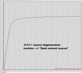
3. If you connect a variable resistor in the source of your simulated J113, and vary it until the output current becomes 6mA, does that I-V curve match the measured data?
2. Why not the other seven? They are just as real.
3. If you connect a variable resistor in the source of your simulated J113, and vary it until the output current becomes 6mA, does that I-V curve match the measured data?
Jeff, you probably know this link ... just in case
EB-604/410 All-JFET Line Amp Starter Kit | audioXpress
EB-604/410 All-JFET Line Amp Starter Kit | audioXpress
Jeff,
I would have to agree with Mark about bipolar current source also the added benefits of cost and predictability.
With regards to the differential I would keep the mirror but add the helper transistor to counter early effect. I think that there are advantages to use a mirror in this application over a current source.
Jam
P.S. So when do we start the build?😉
Attachments
Last edited:
PS: I can't find any indication of what Borbely used there (he just shows a current source symbol), but he does label it D5 (and not Q5), which is probably a pretty good hint.
They were constant current diodes.
I have the part numbers somewhere.
Borbely's current diode of choice.....🙂
He used a lot of J511's.
http://njsemi.com/datasheets/J500 - J511.pdf
Jam
He used a lot of J511's.
http://njsemi.com/datasheets/J500 - J511.pdf
Jam
I tried finding J511's earlier when we first looked at a current source to feed the Zener. Not easy to come by anymore.
Boards are laid out. I'm going to give it a week or so to settle and then order some up.
(I'll post the final schematic later. I need to fix a bug in Kicad to get it to print right....)
Boards are laid out. I'm going to give it a week or so to settle and then order some up.
(I'll post the final schematic later. I need to fix a bug in Kicad to get it to print right....)
Use the bipolar ccs, or use equivalent devices to the constant current diodes, even parallel diodes where necessary.
If accuracy and repeat-ability is important the J511 has a tolerance of +/- 20% which is poor. You can do much better with a bipolar current source and easily adjust the current by replacing one resistor and is cheaper to boot.
Also I would not drop close to the rated across the current diode if you want reliability you need to add a series resistor......not an issue with a bipolar current source.
Jam
Also I would not drop close to the rated across the current diode if you want reliability you need to add a series resistor......not an issue with a bipolar current source.
Jam
- Home
- Amplifiers
- Pass Labs
- JamJar: an HPA-1-inspired power amp