Determination of Damping Factor...........The Easy Way
All we need is a reliable AC VM & a load resistor. And another power amp.
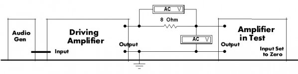
Referring to the attachment, one amplifier is used to drive the output of the amplifier in test. The amplifier in test is not driven, the gain control set to zero.
The driving amp can be any amp of reasonable spec, very little power is required.
Cranking up the signal generator, if 8V appears across the 8R resistor there is One Amp passing thru the secondary of the OPT of the amp in test. Then measure the volts developed across the amp in test secondary terminals. As an example, if that measures one volt the resistance at the amp in test terminals is One Ohm.
If the measurements were made on the 8R tap the Damping Factor is 8/1 or simply 8.
If a second amp is not available on the shelf, call your buddy! And don’t be surprised at the results, might not be as good as you had supposed. SET amps without NFB manage DF of 3 if not biased off too far. SEUL amps without NFB might make DF of one. NFB will push the DF up.
How should I measure the Damping Factor? What equipment do I need for this?
All we need is a reliable AC VM & a load resistor. And another power amp.
Referring to the attachment, one amplifier is used to drive the output of the amplifier in test. The amplifier in test is not driven, the gain control set to zero.
The driving amp can be any amp of reasonable spec, very little power is required.
Cranking up the signal generator, if 8V appears across the 8R resistor there is One Amp passing thru the secondary of the OPT of the amp in test. Then measure the volts developed across the amp in test secondary terminals. As an example, if that measures one volt the resistance at the amp in test terminals is One Ohm.
If the measurements were made on the 8R tap the Damping Factor is 8/1 or simply 8.
If a second amp is not available on the shelf, call your buddy! And don’t be surprised at the results, might not be as good as you had supposed. SET amps without NFB manage DF of 3 if not biased off too far. SEUL amps without NFB might make DF of one. NFB will push the DF up.
Attachments
I just measure the output voltage for a given R load, then replace R with R1 (say 10% apart), measure the output voltage again, and calculate the internal source impedance of the amplifier output. From this you get DF.
I just measure the output voltage for a given R load, then replace R with R1 (say 10% apart), measure the output voltage again, and calculate the internal source impedance of the amplifier output. From this you get DF.
Another way measures the output volts with & without a load. The answer is good enough for a first order estimate. And also shews if the amp is stable.........or not!😱
Yes, I read similar things this evening about measuring the damping factor. Thanks for confirming.
I’m however wondering if every amplifier ‘likes’ to be driven without load. I like the idea of changing the dummy load 10%. From my early years in electronics (40+ years ago) I remember to NEVER run an amplifier without a reasonable load. I don’t think my current amplifier under construction would like to run full power and then disconnect the dummy load... So what power level is reasonable / reliable for these measurements (load vs. no load)?
I’m however wondering if every amplifier ‘likes’ to be driven without load. I like the idea of changing the dummy load 10%. From my early years in electronics (40+ years ago) I remember to NEVER run an amplifier without a reasonable load. I don’t think my current amplifier under construction would like to run full power and then disconnect the dummy load... So what power level is reasonable / reliable for these measurements (load vs. no load)?
6vheater
How do you describe something?
Many common vacuum tube push pull output “stages” have at least the following parts:
A ‘push’ tube (one phase)
A ‘pull’ tube (opposite phase)
A push pull output transformer
Many common push pull output stages cancels, cancels out, or reduces the 2nd harmonic.
Cancels, cancels out, partially cancels, reduces, whatever you want to call it.
And the 2nd harmonic is also affected by negative feedback: cancels, cancels out, partially cancels, reduces, whatever you want to call it.
The output transformer, that is used in this particular topology, that ‘cancels’ or ‘cancels out’ the 2nd harmonic can not do so without both tubes.
The common push pull tube output stage description most often includes 2 tubes, and the output transformer.
The result of the reduction of the 2nd harmonic is usually measured at the output of the transformer.
Yes, operating the tubes in the most linear area of their curves is a good idea.
But if you simply limit the excursion of the stages, that will reduce the 2nd harmonic.
A straight line is comprised of 2 or more points. Consider Euclidean Geometry, and consider 3 infinitesimal sized points forming a straight line. Low excursion, no (extremely low) 2nd harmonic.
I think, even in several places along the tube curve that is an ideal operating area, but there is so little power out.
How many descriptions of a push pull tube stage only speak only about the OPT?
Semantics, Semantics.
Without the push pull output Transformer, the above stage does not work.
push pull becomes a different push pull circuit topology without the OPT.
Instead, you may choose to use a series string of the two tubes, quite often called an OTL stage.
With OTL, the two tubes are not operating with the same parameters (only the quiescent parameters are the same). One is a plate output, and the other is a cathode output. There are no complimentary vacuum tubes I am aware of.
No NPN and PNP tubes; no N-Channel and P-Channel tubes; and no N-JFET and P-JFET tubes.
What was it you said about reducing the 2nd harmonic by operating the tubes in their most linear region?
Therefore, in order to get low 2nd harmonic distortion out of the tube OTL, lots and lots of feedback is required.
Lots of negative feedback also helps to reduce the output impedance of the OTL stage: the cathode impedance is too high, and the plate output impedance is even higher.
This circuit is not optimizing, nor is it utilizing the ‘linear’ operation of the tubes.
I have my preferences:
Push Pull tubes with Push Pull transformer.
SE tube(s) with SE transformer.
In no particular order.
I might even like a Push Pull complimentary solid state output.
Or, a push pull solid state output with matched non-complimentary: NPN, N-Channel, or N-JFET Silicon Carbide devices to drive a push pull output transformer.
I have circuits I do not prefer:
Vacuum Tube OTL.
Also, I do not like hernias either.
All the above is my opinion.
To each his own preference.
Some engineers were not able to understand how a bumble bee flies.
But the bumble bee knows how to do it.
Enjoy the Music!
6vheater,
There are many paraphase invertor amplifiers. I am not sure they are paraphrase, but that is how my spell checker wanted to spell it.
But there are some of those topologies that have a problem.
For some paraphase circuits, the first stage drives a voltage divider which sends that to the second stage (the second stage gives the inverted output). The gain of those two stages can be matched, OK.
But the first stage also has second harmonic distortion, and the second stage's own second harmonic distortion, is out of phase with the signal from the divider's second harmonic distortion that came from the first stage.
I call that serial second harmonic distortion cancellation. The second stage output has little or no second harmonic distortion, compared to the first stages output which does have second harmonic distortion.
That means the second harmonic of the first stage is passed on to the next part of the amplifier.
But the second stage output does not have second harmonic, so it passes a clean signal to the other next part of the amplifier.
If the next part of the amplifier is the push pull output stage, then this is the result:
Push side is presented with a signal that has second harmonic from the first stage in the paraphase invertor.
But the Pull side is presented with a signal that does not have any second harmonic coming from the second stage of the invertor.
The result is that the push pull stage will not cancel all of the second harmonic distortion, because some of that distortion comes only from one phase of the invertor.
I am just sayin'.
Last edited:
One more observation:
An earlier post in this thread said that the paraphrase invertor gives microphonic cancellation.
Well, if a pair of triodes are used, for example, and one has a mechanical resonance at say 1900Hz, and the other triode has a resonance at 2050 Hz, that is not microphonic cancellation.
The best that can happen is the 1900Hz microphonic will be reduced (-3 dB), and the 2050 microphonic will be reduced (-3 dB).
But (-3dB) + (-3dB) = 0dB.
The problem is with one triode, you have 0 dB at only one frequency; but with 2 triodes you now have two different frequencies, the total is still 0 dB.
All that has happened is the same total microphonic level, but with two frequencies instead of one frequency.
Which is better, I will not even attempt to say.
6vheater,
There are many paraphase invertor amplifiers. I am not sure they are paraphrase, but that is how my spell checker wanted to spell it.
But there are some of those topologies that have a problem.
For some paraphase circuits, the first stage drives a voltage divider which sends that to the second stage (the second stage gives the inverted output). The gain of those two stages can be matched, OK.
But the first stage also has second harmonic distortion, and the second stage's own second harmonic distortion, is out of phase with the signal from the divider's second harmonic distortion that came from the first stage.
I call that serial second harmonic distortion cancellation. The second stage output has little or no second harmonic distortion, compared to the first stages output which does have second harmonic distortion.
That means the second harmonic of the first stage is passed on to the next part of the amplifier.
But the second stage output does not have second harmonic, so it passes a clean signal to the other next part of the amplifier.
If the next part of the amplifier is the push pull output stage, then this is the result:
Push side is presented with a signal that has second harmonic from the first stage in the paraphase invertor.
But the Pull side is presented with a signal that does not have any second harmonic coming from the second stage of the invertor.
The result is that the push pull stage will not cancel all of the second harmonic distortion, because some of that distortion comes only from one phase of the invertor.
I am just sayin'.
Ahh, never thought of that !
That might explain why some folks actually prefers paraphase inverter stages!
Thanks for that observation!
Many common push pull output stages cancels, cancels out, or reduces the 2nd harmonic.
We can add to the cancellation of 2H all of the even order, 4H, 6H, 8H, Etc.
For good measure also the zeroth term, DC.🙂
Diff amps with a reasonable size tail also cancel even order harmonics & common mode signals. Even active common mode rejection is possible.
All before SS was common.
We can add to the cancellation of 2H all of the even order, 4H, 6H, 8H, Etc.
For good measure also the zeroth term, DC.🙂
Diff amps with a reasonable size tail also cancel even order harmonics & common mode signals. Even active common mode rejection is possible.
All before SS was common.
Odd order harmonics are more difficult to reduce.
Negative Feedback is one way.
Or you could use a stage that expands the signal according to its amplitude; the larger the signal, the greater the Expansion. Doing that in a smooth and precise way is difficult in the analog world.
Doing that with math and DACs may be easier.
The point is to apply that expanded signal to the output stage.
A push pull output stage typically compresses at the top and bottom of the signal, when the signal level increases there is more and more compression.
That causes the odd harmonics.
Math and DACs anybody?
For PP Pentodes reducing the load impedance carefully can reduce odd order harmonics. I always set the load matching too lower than the data sheet sez, the load is a loudspeaker & will probably go high at each end of the spectrum. The recommended optimum load only works for a load that is a resistor or looks like one...PF=1.
Local NFB such as UL, McIntosh Unity Coupling or Electrovoice Circlotron can be very effective in reducing all distortion while driving active loads such as Loud Speakers..🙂 Just get the driver done right.
Local NFB such as UL, McIntosh Unity Coupling or Electrovoice Circlotron can be very effective in reducing all distortion while driving active loads such as Loud Speakers..🙂 Just get the driver done right.
A push pull output stage typically compresses at the top and bottom of the signal, when the signal level increases there is more and more compression.
No idea where you get that from,- utter nonsense.
Have you ever bothered to use a scope, comparing input with output?
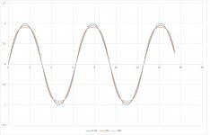
6vheater, why do you respond so rudely? It's not utter nonsense, push-pull distortion is predominantly third harmonic which flattens the top and bottom of the sinewave (see picture), you just can't see it on a scope unless distortion is high. How it looks with a music signal is another matter....
Attachments
That is a completely worn out subject.
Maybe your push pull amp produces lots of odd harmonic distortion, as do very many commercial amps.
Properly designed ones don't, so this sort of generalisation is nonsense, as is the idea that a complex music signal changes anything at all.
If you look carefully the THD of a "typical" PP valve amp increases in a fairly linear fashion, then shoots up as it approaches what looks like fairly soft clipping.
Amps using ultralinear screen grid connections do compress, but it's what appears to be a taboo subject, because the resultant sound -half way house between triode and pentode, so many people seem to like "warts and all".
It was the basis of a whole generation of "smooth sounding" amps especially from the USA & Mullard.
To my mind we don't want to be adding more compression artefacts to most musical signals which already compressed to death.
Solid state amps don't produce the same characteristics,- usually have giant amounts of NFB and are not allowed to come close to clip, at which point they have that brutality of noise, for which they have become well known.
It's as a valve amp approaches clipping that it compresses the signal,- which is why they are routinely used in studios - In push pull would you believe (!) as a balanced pair to add some soft distortion close to clip to make digital sound less harsh.
I wouldn't dream of running any hifi amp constantly even close to clip.
What you get is a pool of mud!
Citing posts 52 and 54.
6vheater, which answer is your answer?
your responses innthe cited posts are almost diametrically opposed.
Which is it? (Your opinion)
PP close to clip do, or dont compress the peak of the sine?
I know my opinion:
A increase in 3rd Harmonic will show itself on a scope as a flattening to the sine wave peak.
Irrespective of the typology of the amplifier
Increasing ever further the sine wave peak is inverted, where there was a peak, is now a dip and the amplitude maxima form 2 peaks centred about the fundamental peak.
Anyone who spent any time on a scope, would understand perfectly what was meant by compression....
Increasing ever further the sine wave peak is inverted, where there was a peak, is now a dip and the amplitude maxima form 2 peaks centred about the fundamental peak.
Anyone who spent any time on a scope, would understand perfectly what was meant by compression....
Sorry it's rubbish.
When you approach clip, the peaks of the sine wave FLATTEN.
(it's normal, the valve curve goes over kink into non conduction, unless of course you run in AB2, where another secondary virtual anode forms from the control grid.).
If you push a valve amp further into clip the peak of the sine wave doesn't INVERT it simply turns into a square wave. You wanna see the traces I have of exactly that?
Again it's a case of "grandmother" and "sucking eggs", - what's more I record the output of the amp into the dummy load into a DAW, so it can be retrieved at an instant's notice.
For those of us who deliberately test valve amps at full load for long periods, we might just have some idea of the relationship between input and output...graduated in fractions of a dB. (you can manage that sort of precision with a DAW).
I can assure you there is no such thing as the compression you claim.
I've spent a lot of time measuring it, - disproving theories and claims from some quite well known people deliberately. (eg. claims of compression using CFB turned out to be totally false).
Only for those who are interested:
Spectrum analyzers do not lie.
Well, they will lie if you set them up improperly.
And they will lie if you use them beyond their specified measurement limits.
“All generalizations have exceptions”
In light of that quote, consider the following:
Single stages, SE and Push Pull, without negative feedback applied:
For a stage of a single ended triode:
The stage has dominant 2nd harmonic distortion, and a lower level of 3rd harmonic distortion.
With a pure sine wave input, the apparent shape of the output wave is a ‘fat' shortened alternation, followed by a ‘thin' taller alternation.
Many single ended amplifiers exhibit this characteristic (especially if there is no cancellation from earlier stage(s), and no output transformer saturation).
Before we approach clipping, this becomes visually apparent on an oscilloscope.
If we have a spectrum analyzer, it is easy to verify the fact of the harmonic amplitudes.
For a stage of two triodes in push pull mode:
The stage has dominant 3rd harmonic distortion, and a lower level of 2nd harmonic distortion.
With a pure sine wave input, the apparent shape of the output wave is a ‘fat' shortened alternation, followed by another ‘fat' shortened alternation.
Many push pull amplifiers exhibit this characteristic (especially if there is no cancellation from earlier stage(s), and even if there is no output transformer saturation).
Before we approach clipping, this becomes visually apparent on an oscilloscope.
If we have a spectrum analyzer, it is easy to verify the fact of the harmonic amplitudes.
If we go to hard clipping with either the single ended stage, or with the push pull stage, we begin to approach a square wave.
A pure square wave has the fundamental and all odd harmonics.
The harmonic voltages fall off at the reciprocal of the odd harmonic number, 1/3, 1/5, 1/7, etc.
The higher and higher harmonic number’s power become very small (at the rate of the square of the voltage (1/3) squared, (1/5) squared, (1/7) squared, . . . etc.
If the rise time and fall time of the square wave is limited, that limits the top odd harmonic numbers that are contained in the square wave.
Now, suppose that the square wave is asymmetrical (more time in one direction than time in the other direction; up time versus down time).
In addition to all the odd harmonics, we also get all the even harmonics: 2nd, 4th, 6th, etc.
But all these even harmonics are at the same level (the level depends on how asymmetrical the square wave is). This is not really a square wave, it is a pulse.
If the rise time and fall time of the pulse wave is limited, that limits the top odd harmonic and top even harmonic numbers that are contained in the square wave.
When do we call a square wave a pulse, and when do we call a pulse a square wave? Asymmetrical at 0.5%, 2%, 5%, etc.?
The other factor of the asymmetry is, the odd harmonics amplitudes are falling at higher frequencies, but at the same time, the even harmonics amplitudes are not falling at higher frequencies.
Although the 3rd harmonic is stronger than the 2nd harmonic, we eventually get to a point where the remaining even harmonics are stronger than the remaining odd harmonics.
For example, the even 10th harmonic may be stronger than the odd 9th harmonic, etc.
Last edited:
I say so what?
All that stuff can't even get close to the awesome computing power of a proper DAW (A digital audio workstation) if you heard of it.
Lots of the PC sound cards these days are pretty capable stuff, with low noise, low distortion, and often outstandingly good DAC, very often better than the expensive "hi end" discrete ones people like to buy.
You can process the input and output waveforms in real time, display FFT calculations in real time, and superimpose the input and output waveforms on top of each other in real time.
Superimposing one waveform on top of another isn't good enough?
It is for me.
I certainly don't see the kind of nonlinearities you describe on my amps.
Maybe you should move away from SE amps and poor quality PP amps that are knocking out 2-4% THD with no NFB?
Are you seriously telling me those millions of calculations per second from a modern multi ghz CPU, can be beaten by the kind of generalisations you made and the equipment you are describing?
Modern computing can perform high performance calculations in real time which you can't,- no matter how good the displays show on an old 'scope.
FYI:-
On this forum is a group that has developed a pure software distortion measurement system.
The resolution is stunning, and the performance is amazing.
FYI, I use old style scopes and distorion meters for performing rough and ready comparisons.
The DAW actually records the entire audio session from start to finish if I want in 24bit res.
That means you can virtualise a lot of the hard work of analysis and redesign when the amp is not even on.
Most of the stuff you wrote above is completely irrelevant to working on real amplifiers with real high quality transformers, real matched valves, and high linear power outputs.
As a matter of interest, did you ever measure one of the better Fisher amps?
I wouldn't exchange a Fisher Sa-1000 for anything, if I could actually get one, it's a superb PP design, and doesn't match a single one of the criticisms you level above.
I agree with the description:-
1963
All that stuff can't even get close to the awesome computing power of a proper DAW (A digital audio workstation) if you heard of it.
Lots of the PC sound cards these days are pretty capable stuff, with low noise, low distortion, and often outstandingly good DAC, very often better than the expensive "hi end" discrete ones people like to buy.
You can process the input and output waveforms in real time, display FFT calculations in real time, and superimpose the input and output waveforms on top of each other in real time.
Superimposing one waveform on top of another isn't good enough?
It is for me.
I certainly don't see the kind of nonlinearities you describe on my amps.
Maybe you should move away from SE amps and poor quality PP amps that are knocking out 2-4% THD with no NFB?
Are you seriously telling me those millions of calculations per second from a modern multi ghz CPU, can be beaten by the kind of generalisations you made and the equipment you are describing?
Modern computing can perform high performance calculations in real time which you can't,- no matter how good the displays show on an old 'scope.
FYI:-
On this forum is a group that has developed a pure software distortion measurement system.
The resolution is stunning, and the performance is amazing.
FYI, I use old style scopes and distorion meters for performing rough and ready comparisons.
The DAW actually records the entire audio session from start to finish if I want in 24bit res.
That means you can virtualise a lot of the hard work of analysis and redesign when the amp is not even on.
Most of the stuff you wrote above is completely irrelevant to working on real amplifiers with real high quality transformers, real matched valves, and high linear power outputs.
As a matter of interest, did you ever measure one of the better Fisher amps?
I wouldn't exchange a Fisher Sa-1000 for anything, if I could actually get one, it's a superb PP design, and doesn't match a single one of the criticisms you level above.
I agree with the description:-
Year?The Fisher SA-1000 is a legendary tube amplifier - right up there on the "Holy Grail" list of HiFi pieces that every audiophile must own at some point. Power output: 58 watts per channel into 8Ω (stereo)
Frequency response: 7Hz to 30kHz
Total harmonic distortion: 0.11%
1963
Last edited:
The Fisher SA-1000 has negative feedback.
Multiple loops of negative feedback.
Some of the noobs in this forum do not have the facilities to design and build a Fisher SA-1000.
And many of us do not have the money to purchase a DAW (or the time, knowledge, and effort set it up to do what it can do), or some money to purchase a classical tube amplifier that costs 10x its original price.
A few on this forum are able to enjoy the music, even if they do not have the best equipment, best recordings, best knowledge.
Some are not prepared to use lots of negative feedback, and nested negative feedback loops.
The ingredients of a common fire are:
Fuel, Oxygen, extreme heat.
The ingredients of an oscillator are gain, feedback, and either resonance or phase shift (or both). Sounds just like some unsuccessful amplifiers that give problems to posters on this forum.
With limited knowledge and experience, some will:
Build an amplifier, and get an oscillator.
Build an oscillator and get an amplifier.
The readers and posters on this forum are at all kinds of knowledge levels.
A specialist learns more and more about less and less, until he knows everything about nothing.
A generalist learns less and less about more and more, until he knows nothing about everything.
Fortunately, most of us fall between those two extremes.
Last edited:
Given its brevity, only 30 posts, I'd be tempted to rate this as one of the silliest threads in quite a while...
I don't think it is a prize winner, but it isn't getting any less silly at 60 posts. Two or three members rudely and vigorously AGREEing that peaks flatten, but using different words.
- Home
- Amplifiers
- Tubes / Valves
- THD measurements