I am writing this on my DAW, at the same time I am listening to the BBC mpeg stream live online, via a 3g/4g mobile wireless connection, it is also working as a router for my LAN.And many of us do not have the money to purchase a DAW (or the time, knowledge, and effort set it up to do what it can do), or some money to purchase a classical tube amplifier that costs 10x its original price.
It is a notebook with a professional sound card, and dual boot win32/Linux.
What could possibly be so difficult about that?
I routinely use it for high quality live 24 bit recording as well as editing, then I fold it up put it under my arm and catch a flight for 3hrs to some other place where it's has to double as mail centre and wifi access point.
My 1960s amps I bought for 200USD and totally redesigned and upgraded them.
I have a few more of those kind of amps, one pair of which is from 1955 and has PP 6V6 inside.
They are not even fixed bias!
I think I paid 200USD for those pair of monoblocs too.
They sound brilliant, weigh not a lot, and can be abused to death.
When I measured them they also had good figures and an astonishingly good frequency response.
The best way to learn to paint, - as Turner would have shown you, was first to copy what others do.
The best way to learn about linearity, NFB and all the other interesting things in audio is to look at how others have done it before.
Restoring other people's stuff is a good start..eg. finding out what goes wrong
Waffling on about very vague theoretical ideas such as compression which doesn't exist, SETs, PP amps, and how nice even harmonic distortion might be (it's not it's MUD), is fundamentally unhelpful as a way to understand why so many 50s and 60s amps sound so much better than modern ones.
Regardless of whether it's possible or useful to copy a Fisher SA1000, doesn't get around the fact some stuff sounds good, and some doesn't.
Lots of this modern stuff sounds terrible.
All this is not magic or rocket science, it's about the right kind of linearity where it matters, and what may not neccessarily measure so well,- may sound a lot better than something like say a MAC, simply because those sound horrible and dead with mountains of feedback.
Today, I suspect the guys doing screen drive or "crazy drive" on old TV valves might just have got it right.
Making good food is not about throwing every ingredient in a pot and saying how wonderful it will be..
I get that in professional recording constantly, using 50 microphones to record something which only requires 4 placed in the right locations..
Too much salt spoils the soup.
Last edited:
Something Worth Knowing
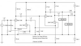
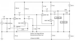
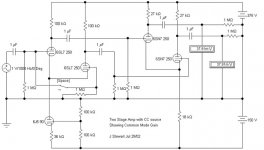
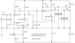
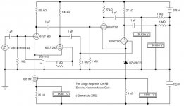
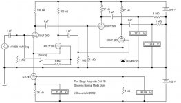
Cutting away from the various discussions of what is & what isn't, here is a series of six simulations covering the normal mode & common mode gain of a 2-stage toob amplifier.
There is no test after this.
The first of these examples uses simple resisters to a -ve rail of 150V. It shews a normal mode gain of ~116 to each of the outputs. The common mode gain is 0.382.
The 2nd example replaces the resister tail of the first stage with a triode whose tail is yet another resister. In this case the tail for the first stage looks like (20 + 1)*36K or 756K. That is about 10X the simple resister tail. The common mode gain drops to ~0.038. And the normal mode gain still ~116.
The 3rd circuit uses an active FB connexion from the cathode of the 2nd stage. To avoid using a resister network to shift the DC level a zener is shewn. But just as easily that could be replaced by a 75V gas regulator. The result is a common mode gain of ~0.036, while the normal mode gain has increased to ~124. Not much improvement that time.
For those still awake, you can calc the common Mode Rejection Ratio(CMR) from
20 log (Normal Mode Gain / Common Mode Gain)
Please be kind to those who haven't seen this sort of thing before. And please don't tell me you could do it better. So can I!😀
Attachments
Sorry it's rubbish.
When you approach clip, the peaks of the sine wave FLATTEN.
Funnily enough, this was exactly what I said.
The inversion of the peak, is indeed what I see on a scope, looking at a source with fundamental and 3rd harmonic only, or dominant 3rd harmonic.
Hopefully not a condition youd see on an amplifier, it wouldnt be very listenable.
But very common and easily seen on voltage waveforms of AC generators (which are also tested for THD (or rather HD to the 100th Harmonic)
The point I am making is:
There is a big difference between waveform distortion due to THD generation in a voltage generator/amplifier; and clipping of the sine, due to overdrive/overload.
They arent one and the same.
There is a big difference between waveform distortion due to THD generation in a voltage generator/amplifier; and clipping of the sine, due to overdrive/overload.
They arent one and the same.
jhstewart9
Looking at your 6 diagrams I’m wondering if you have their THD measurements perhaps. I would be interested to see what the performance differences are. For example differences in mainly even / odd harmonics?
Looking at your 6 diagrams I’m wondering if you have their THD measurements perhaps. I would be interested to see what the performance differences are. For example differences in mainly even / odd harmonics?
Hi all,
As I continued testing and measuring I found a few 'sweet' spots regarding THD from my signal generator. I found that at 335 Hz. and 667 Hz. @0.5V RMS I measured a THD of 0.04% instead of 0.18 - 0,22 % for other frequencies/output.
When measuring my amplifier using these sweet spots I similarly get lower THD measurements, around 0.10% @36 Watt output. For non-sweet spots I get a higher THD around 0.30 %.
I guess this makes some sense. After all, harmonics that came in cannot be ignored when amplified.
I know these two tones don't make the music, but I wanted to share these results with you. I guess most signal generators will show different THD values for certain frequencies and output, but I only have a Velleman unit at present, so I cannot compare right now.
Regards, Gerrit
I have found that my lab signal gen, which isnt audio grade, has a variable THD in its output.
I havent found that it changed with regard to frequency, as I havent tested it - it is a Agilent digital function generator of a fairly modern vintage.
I have found that the unit needs 30 mins warm up for the output THD to stabilise at its minimum level.
Even then, however, the THD is between 0.1% and 0.3%, 2nd and 3rd harmonic only.
That explained why, a few months ago, I was puzzled by THD repeat tests of a circuit which varied by the same amount - 0.2-0.3%
Now as long as I can achieve <1% as measured, I know that I can rely on readings- if I was aiming for 0.1% THD, then my measurements would be uncertain. read: nonsensical
Last edited:
Hi Innergy,
Of course this depends on circuitry and the level of output power. I guess anything below 0.5% is very good for SET.
Regards, Gerrit
Of course this depends on circuitry and the level of output power. I guess anything below 0.5% is very good for SET.
Regards, Gerrit
jhstewart9
Looking at your 6 diagrams I’m wondering if you have their THD measurements perhaps. I would be interested to see what the performance differences are. For example differences in mainly even / odd harmonics?
Late responding, real things need to get done here at home.🙂
The examples given are simulations. The models given in Electronic WorkBench (EWB) software are only first order. So any D% numbers don't mean much, need to build a real cct & do the tests. Very much depends on matching of the triodes so better results with dual triodes should be the case.
I've used the two tube diff amps with simple resistor tails to -150V as drivers in several projects with very good results. It is easy to build in AC balance into the cct, then adjust that for least 2nd harmonic of the entire amp.😎
The usual cct uses 6SL7 as first stage, 6SN7 as 2nd stage. All these were bootstrapped drivers into output stages like the ElectroVoice/Circlotron, Norman Crowhurst's Twin Coupled/McIntosh clone & a PPP 6080 output stage (25W).
I built a pair of adapters to try 6BQ7/6BK7 family in these drivers. The results measuring both THD & IMD were a lot better than most people would expect.😱
Attachments
check out PDF files in post #82 under
https://www.diyaudio.com/forums/sol...ooks-overview-google-books-9.html#post6707846
https://www.diyaudio.com/forums/sol...ooks-overview-google-books-9.html#post6707846
- Home
- Amplifiers
- Tubes / Valves
- THD measurements