1) in merger tool, do i have to compensate for the fact I used less than 2.83 volt or is it ok to leave number as they are even if lowish?
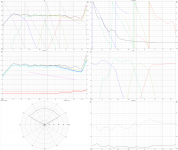
2) I simulated the crossover and the on axis spl trace does not match the measurement I made with the crossover, it has a dip of circa 3db from 1.2Khz to 6 khz, if I apply the delay it is even worse. Is it a phase issue that shall be dealt with in the merger?
1) Scaling of HF part (far field responses) in Merger tool is not recommended to maintain SPL/sensitivity difference to responses which are not merged e.g. tweeter, assuming that far field responses of all drivers are measured at the same distance (1000 mm) using the same voltage. SPL scaling of drivers can be done in Drivers tab @ program while XO simulation if you prefer SPL (dB/2.83V/1m) readings in SPL charts, but your measurement system and settings do not provide that "automatically".
2) Possible timing issue between measurements of different drivers is almost impossible to solve remotely from here. You just have to follow measurement instructions written for REW; make dual channel connection, select correct options in REW and measure at the same distance from baffle surface to mic with tha same voltage. You should at least inform in details if something was not done or set according instructions, that others could guess possible error sources.
And finally, if you like to compare simulated total axial response to measured total axial response, Listening distance in Options window must be set to measurement distance (1000 mm) and relative Y coordinate of drivers should match between reality and simulation in order to get comparable results. Generally, comparison to sum measurement is not needed and recommended assuming that instructions are followed.
Referring earlier discussion about measured off-axis angles: 0-90 deg with Half space checked or 0-180 deg and Mirror missing are needed to get correct off-axis, power and DI results.
Last edited:
A basic question: i am simulating an enclosure for Seas W26FX001. I have measured the impedance and TS-parameters using DATS V3. In enclosure tool, at what Voltage can i see Cone excursion and port velocity exceeding the woofers limit? This woofer is rated at 150 Watt long term power handling. Do i use the power graph to see when i have raised the voltage to 150 Watt?
Usually Xmax is exceeded way before Pmax. Just increase voltage step by step from 2.83 V up to 150 W to nominal impedance of 8 Ohms =sqrt(150*8)=34V and monitor which one hits the limit first. I guess Xmax=7mm is reached with about 16 V / 37 VA with vented enclosure (QB3 Ql=7).
Some other case you can look also Power chart.
Last edited:
Simulated vs Reality impedance.
I've been playing around with Linkwitz 4th order on a 4-way loudspeaker. Imported the graphs from the data sheets.
Tweeter and midrange is 6 ohm while mid-woofer and woofer is 8 ohm.
While this is not a real loudspeaker in terms of diffraction etc. My concern is the impedance dip. It goes as low as 1.8 ohm.
Is this a reflection of real situations ???
Is there a way to work with 4th order and maintain a good impedance response ?
Attachments
Is this a reflection of real situations ???
Is there a way to work with 4th order and maintain a good impedance response ?
Usually no, but of course it is possible to design XO so that power is burned in resistors without producing as much sound pressure as possible. Replace possible L-pads with series resistor only and avoid high Q low and high pass sections (hump close to HP / LP frequency visible in Filter chart). Match phase better and forget 4th order for the lowest XO points which is not so valuable especially as passive.
Thank you for that valuable answer. I know things will be different when doing a real XO and measurements.
A question from a beginer
In order to use this fantastic software do I need and acoustic laboratory as my first explorations of the software let me guess.
Or is it possible to use data or graph extracted from driver datasheets.
Regards,
Stéphane
In order to use this fantastic software do I need and acoustic laboratory as my first explorations of the software let me guess.
Or is it possible to use data or graph extracted from driver datasheets.
Regards,
Stéphane
Ideally you measure loudspeakers like bartosz37 said.. but if you wana play with producing filters, learn and see the effects of what you do, you can absolutely import the graphs from datasheet's. That's what I do as an exercise 🙂
Ok the problem is that an acoustic laboratory to perform reliable acoustic measurements is more in the budget of an industrial rather than a diy player.
That is why you need to do near- and far field measurements as well as ground plane measurements. Even anechoic chambers are only good down to say 100Hz. Good measurements even with a million dollar room has its challenges.
It takes time to collect info on how to and different engineers have different methods (compensation). When it comes to equipment, well, that is down to what you are willing to spend.
Dayton Audio has some okayish starter products you can use. At the end of the day, it all depend on if you wana build just one pair of loudspeakers and be done with it or if you wana experiment and improve. There is always the replica you could go for if you know the drivers and XO and can estimate the internal volume.
Building loudspeakers has and will always be a challenge - so, you can do it the simple way: Buy ready made, do a kit or replica OR you are set to become an engineer. I've been studying for well over 4 years and I'm not done by a long shot, I will probably never be fully done as there is always something new to try or discover. But that is a charm in itself.
Start simple. Start with a 2-way, figure out the measurement equipment you wana start with and slowly improve the performance through various XO's and ways of measuring it, including listening to it 🙂
SMourareau, there are many threads around here on loudspeaker measurement and the techniques and equipment needed. Google "quasi-anechoic measurements" etc, look at the ARTA-thread in the Multi-Way forum. Read Kimmo's own pdf from his website on measurements.
VERY few people have "labs" at home 🙂 What we have is gated measurements.
VERY few people have "labs" at home 🙂 What we have is gated measurements.
Exactly 🙂 I am lucky enough to be able to rent one of very few anechoic chambers in Europe, the one at KTH in Stockholm. But even if I where to measure there, its not a guaranty bellow 200Hz, which is the issue for everyone. SO might as well do gated measurements and save my money 🙂VERY few people have "labs" at home 🙂 What we have is gated measurements.
Capturing from datasheets is so invaluable due to obvious error sources related to directivity and required post processing to get full space from half space data that I would not recommend it for anybody. Not even for practicing filter designing (which is possible with impedance responses only).
I measure in our living room (25 m2) with gating also commercial products no matter mechanical size and price tag. Special and new directivity concepts could need much larger space.
I measure in our living room (25 m2) with gating also commercial products no matter mechanical size and price tag. Special and new directivity concepts could need much larger space.
Found it.
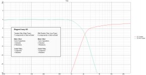
Just wanted to share my discovery of the day. Perhaps one of the most elegant and simple filters This is not a reflection of real life since the Fr.response and impedance are imported from data sheets.. however, this was about trying a new filter (see amount of components) and what it did to the phase and impedance.
After years of looking at orders, filter types etc. This is by far one of the best days in my loudspeaker endeavors. Having patience truly pay's off 😀
Info.
6 ohm tweeter and 8 ohm mid-woofer. The XO impedance never goes bellow 3.8 ohm.
Attachments

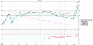
^There's no BSC so you'll probably need few more components in practice to reduce SPL by 3...5 dB if that's 2-way full space application.
I am not sure if you have been asked this before.
Is there the possibility of having the option of chamfers instead of roundovers in the diffraction tool?
And setting the size of the bevel/radius separately for each of the four sides on a common box?
Is there the possibility of having the option of chamfers instead of roundovers in the diffraction tool?
And setting the size of the bevel/radius separately for each of the four sides on a common box?
I've been playing around with Linkwitz 4th order on a 4-way loudspeaker. Imported the graphs from the data sheets.
Tweeter and midrange is 6 ohm while mid-woofer and woofer is 8 ohm.
While this is not a real loudspeaker in terms of diffraction etc. My concern is the impedance dip. It goes as low as 1.8 ohm.
Is this a reflection of real situations ???
Is there a way to work with 4th order and maintain a good impedance response ?
Usually no, but of course it is possible to design XO so that power is burned in resistors without producing as much sound pressure as possible. Replace possible L-pads with series resistor only and avoid high Q low and high pass sections (hump close to HP / LP frequency visible in Filter chart). Match phase better and forget 4th order for the lowest XO points which is not so valuable especially as passive.
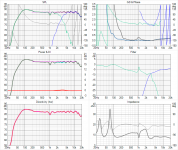
I don't understand this comment. Why should a 4th order Linkwitz Reily crossover necessarily cause such a severe impedance dip ?
I have a 4th order Linkwitz Reily crossover in my two way system (designed in VituixCad) both drivers are nominally 8 ohms (8.2 woofer, 7.5 tweeter) and the lowest impedance point of the entire system is 7 ohms, at the crossover frequency, and it only dips this low because I have deliberately tuned the low pass filter to "peak" slightly (acting as an impedance transformer at resonance) to compensate for a slight driver hole at 3Khz. If I had not done this it would not have dipped as low as 7 ohms.
While it's typical for the summed impedance to dip a little bit below the driver impedance a dip as large as described sounds like a problem with the crossover design IMHO, and that it can be reworked to get the same transfer function without such a low input impedance.
Edit: correction, it dips to 6.8 ohms.
Attachments
Last edited:
Is there the possibility of having the option of chamfers instead of roundovers in the diffraction tool?
I'm not so keen to add support for chamfers, though it is very common option. Calculation doubles down with the 1st order diffractions only (without some approximation/workaround).
And setting the size of the bevel/radius separately for each of the four sides on a common box?
Individual radius is not impossible either, but that can't be just for typical four edges. All 35 possible edges should have individual radius property which would require modified user interface with multi-selection of edges (not corners).
I'm not saying No, but these could take some time with current motivation.
- Home
- Design & Build
- Software Tools
- VituixCAD