I own a Behringer DCX24x96 pro (modified).
For the moment, I use analog outputs in order to feed a two ways pairs of speakers.
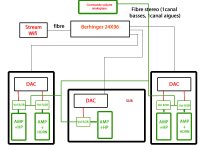
I would like to use digital links between the filter and the speakers, with one simple DAC inside each enclosure.
I'm looking for way to mix two mono digital outputs in the DCX to a stereo one, the target is to have the canal left transmitting the basses and the right the treble ? One link, one DAC for one speaker's enclosure.
Thank in advance.
For the moment, I use analog outputs in order to feed a two ways pairs of speakers.
I would like to use digital links between the filter and the speakers, with one simple DAC inside each enclosure.
I'm looking for way to mix two mono digital outputs in the DCX to a stereo one, the target is to have the canal left transmitting the basses and the right the treble ? One link, one DAC for one speaker's enclosure.
Thank in advance.
It would not be a mix. Mixing is completely different to what you need which is shuffling.
Easiest would be to buy a 4in 4out digital audio shuffler. It allows you to route any of the 4 inputs to any of the 4 outputs
Easiest would be to buy a 4in 4out digital audio shuffler. It allows you to route any of the 4 inputs to any of the 4 outputs
Thanks a lot.It would not be a mix. Mixing is completely different to what you need which is shuffling.
Easiest would be to buy a 4in 4out digital audio shuffler. It allows you to route any of the 4 inputs to any of the 4 outputs
No way to build some in mY DCX ?
Last edited:
Thanks a lot.
No way to build some in mY DCX ?
If I understand correctly - the DCX only has analog outputs, but you want digital outputs after the DSP?
It's in theory possible. You would need to tap the I2S or TDM pins that feed the AK4393 DACs and add a small PCB with an SPDIF transceiver or some other method to drive a long cable. I have no idea if you could easily fit it or if there are test points to make it easier.
Thanks a lot.
No way to build some in mY DCX ?
Sure there is. If you know how.
Yes, (Thanks chris719), but a little more. I would like to can send after the DSP that is used as an active filter, in one single optical link the bass and the treble of one of the input stereo channel for they can be decoded by a simple standart DAC in my speakers enclosures: left basses, right trebles.If I understand correctly - the DCX only has analog outputs, but you want digital outputs after the DSP?
If I'm Comfortable with analog, i'm a newbie in digital design ;-) (But i learn fast ;-)
The idea is to have no grounds leakage between the speakers and the sources.
Attachments
Last edited:
Does the DCX already output your bass to left and treble to right channel analog outputs?
If so, then you only really need something like one TI DIT4192 or AKM AK4104 for each pair of channels.
http://www.ti.com/lit/ds/symlink/dit4192.pdf
See Figure 14 to see how it's interfaced with a Toslink transmitter. You'll also need a simple microcontroller to configure the chips. I don't know if there are any that are still in production that are controllable via hardware without a I2C or SPI interface.
If i remember well, there is 4 possible assignations. (for outs 1 to 6) No notion of stereo for the out.Does the DCX already output your bass to left and treble to right channel analog outputs?
Mono in -> Sub+L+LM+M+HM+H
Stereo -> L+M+H + L+M+H
Stereo -> L+L+M+M+H+H
3 ways -> L+H+L+H+L+H
Plus the one that I will use. M+H (left), M+H (right), L(left + right), unused.
If I remember well too, it use 6 DACS.
I have to look at this, I just found at the instant via Gougeule.
DCX2496 mod for Digital OUT x 3
Last edited:
If i remember well, there is 4 possible assignations. (for outs 1 to 6) No notion of stereo for the out.
Mono in -> Sub+L+LM+M+HM+H
Stereo -> L+M+H + L+M+H
Stereo -> L+L+M+M+H+H
3 ways -> L+H+L+H+L+H
Plus the one that I will use. M+H (left), M+H (right), L(left + right), unused.
If I remember well too, it use 6 DACS.
I have to look at this, I just found at the instant via Gougeule.
DCX2496 mod for Digital OUT x 3
Yes, this is also what I suggest except he's using CS8404 which is obsolete. Helpful that he's already identified where to tap. There are 3 AK4393 DAC chips. They are stereo, so 6 channels total. You just need to bring the master clock, bit clock, word clock, and data signals to each SPDIF transmitter. The Toshiba TOTX173 is also obsolete, but I believe there is an alternative that is still available from another company.
Thank-you for your nice help, both of you.
So it seems to be doable and will bring a lot of benefits, including to get rid of the poor analog stages of the DCX (already upgraded).
Of course, I suppose the PSU of the DCX has to be upgraded too, as it is deemed to be fragile.
So it seems to be doable and will bring a lot of benefits, including to get rid of the poor analog stages of the DCX (already upgraded).
Of course, I suppose the PSU of the DCX has to be upgraded too, as it is deemed to be fragile.
T.,
May I ask what actual DACs will be at the speakers?
Do those DACs already have optical inputs (presumably TOSLINK)?
May I ask what actual DACs will be at the speakers?
Do those DACs already have optical inputs (presumably TOSLINK)?
Yes you can.T.,
May I ask what actual DACs will be at the speakers?
It was for the pleasure of the joke. I have not decided yet. But I will read your suggestions. For the moment, I use passive filters in my speakers, or analog outs of my modified DCX.
Okay, thank you.
And then the optical fiber you are thinking of is standard TOSLINK, or something else?
If TOSLINK you will probably be limited to 24/96, although 24/192 might barely work. Also, you might want to do some processing to remove jitter picked up along the way using the (TOSLINK?) optical interface.
And then the optical fiber you are thinking of is standard TOSLINK, or something else?
If TOSLINK you will probably be limited to 24/96, although 24/192 might barely work. Also, you might want to do some processing to remove jitter picked up along the way using the (TOSLINK?) optical interface.
Toslink seems to be the easiest way, don't you think? (DCX is 24/96)And then the optical fiber you are thinking of is standard TOSLINK, or something else?
If TOSLINK you will probably be limited to 24/96, although 24/192 might barely work. Also, you might want to do some processing to remove jitter picked up along the way using the (TOSLINK?) optical interface.
The clock of the DCX is not so good as well. Can't-i rely on the future DAC to take care of it ?
Last edited:
Can't-i rely on the future DAC to take care of it ?
The ESS Sabre DACs have an internal ASRC to attenuate incoming jitter. Usually sounds best if the jitter is very small to begin with since otherwise the DPLL bandwidth will have to be left at a wide setting (assuming there is any user control of it). Lowest possible DPLL bandwidth sounds less distorted, and ESS recommends to set it at the lowest stable value. Most Sabre DACs leave it set at the default, unfortunately (seems to me anyway).
The other main alternative for jitter suppression would be an ASRC chip such as perhaps SRC4392 or AK4137, possibly used along with a AKM DAC chip. Possible to use a Sabre DAC after an external ASRC too, but can be tricky for getting the best sound (although Benchmark DAC-3 does it).
There are Chinese boards one can buy to provide all the needed functions for an AKM dac with external ASRC, or an entire Sabre dac can be had starting around $99 for Khadas tone board. Some people rave about them, but not me (although they are well engineered for the price point). Don't know if they support SPDIF (TOSLINK) though, have to check on that. Pretty sure no way to set DPLL bandwidth to minimum stable value.
I had never understood this PLL problem. Don't they use a first in first out memory loop to get rid of any jitter: The PLL could be slow enough to be rock stable once he will adjust the oscillator frequency to match the average speed. And their is no problem of the delay, here.
Last edited:
I had never understood this PLL problem. Don't they use a first in first out memory loop to get rid of any jitter: The PLL could be slow enough to be rock stable once he will adjust the oscillator frequency to match the average speed. And their is no problem of the delay, here.
It's a tiny FIFO in an SPDIF receiver usually, but it depends on the exact model. It's usually not more than a few samples because no one wants a long delay. The PLL loop filter corner frequency is usually not super low to facilitate quick locking.
IMO this is not a problem like Mark is making it out to be. Jitter is an overblown bogeyman.
I would suggest you use the TI SRC4392 in the DAC portion if you're designing it yourself. It's both a decent SPDIF receiver and ASRC in one chip which will bridge the two clock domains and allow you to use a single local master clock to clock the DAC.
IMO this is not a problem like Mark is making it out to be. Jitter is an overblown bogeyman.
Its that you don't seem to be as picky about sound quality as I am. Jitter is only one of the things that detracts from sound quality though. No point in going all out on only one parameter and not any of the others.
- Home
- Source & Line
- Digital Line Level
- Digital mix question