This might be a dumb question, but the floating supply, is it a dual rail (+/-26Vdc) without the ground wire connected?
Let's say the rectified voltage from a transformer is too high, would it be ok to use say a TPS7A4700 and TPS7A3301 regulator board and leave the gnd NC? Given that the vreg is ok working like that.
Let's say the rectified voltage from a transformer is too high, would it be ok to use say a TPS7A4700 and TPS7A3301 regulator board and leave the gnd NC? Given that the vreg is ok working like that.
It is floating in that it is not connected to the TDA1541A grounds. A dual rail supply is not required.
In my build, I used a LM317 regulator to arrive at 26VDC, and I am very happy with the sound of my D3. The board itself has plenty of regulation so my supply just provides some pre-regulation.
In my build, I used a LM317 regulator to arrive at 26VDC, and I am very happy with the sound of my D3. The board itself has plenty of regulation so my supply just provides some pre-regulation.
Thanks for clearing that up.It is floating in that it is not connected to the TDA1541A grounds. A dual rail supply is not required.
In my build, I used a LM317 regulator to arrive at 26VDC, and I am very happy with the sound of my D3. The board itself has plenty of regulation so my supply just provides some pre-regulation.
I have a few choices then, without having looked at their datasheets; LT1083CP, LT1963, LM317, that's what I have a bunch of each ready to go.
I will use a small TPS7A4700 board for the attentuator circuit, or LT3042? I recall Ryan writing there was not that much to gain from something ultra low noise there.
I'm almost done with Salas TDA1541A shunt reg, PCB by ecdesigns, but I I'll try that in a Red Baron board/boards.
Trying to get a differential parallel TDA1541A up and running at some point, preferably without losing OS(I know I know, but I like OS...just not the SAA7220P/B.
What sort of VA rating is needed if using one transformer only to power the D3?
I know it's probably overkill, but I have several 12-0-12vac 1.5A EI core transformers. I figured using one of those without the CT. Should give 0-24vac if my fever isn't too bad lol
That is a bit on the high side, but the next step down that I have is single secondary 0-9vac so not really an option.
I/V
Hi there, long time no posts 😉
I was wondering what kind of I/V stages those that have built this DAC are using? Those in the process of building or planning to build, what are your plans for I/V?
I have a few options available:
Pedja's DDNF (layout by ecdesigns)
Jfet/triode (my layout)
A DDNF (for my own personal use) with SMD's that is in the layout stage.
Jocko's I/V (I'd have do layout as I'd use SMD's)
I found a schematic via Google using the BF862 and a +5V supplied ground reference that is to be trimmed via a pot to 0Vdc between the reference gnd and the output.
I have some first revision boards for the BF862 I/V.
(Not for sale as I have no idea who designed it,and haven't been able to get permission, I figured it is ok for me to make boards for personal use).
Then there's the opamp route, not to be scoffed at if implemented correctly with good opamps.
I think that covers what I have available or can have available in a reasonable timeframe.
I'm using an active discrete I/V to tube buffer. IMHO, an active buffer is what this chip needs. Once I tried a properly designed cathode follower I never wanted to go back to discrete only. However, the key is that the I/V is done by transistor: a tube I/V feeding a cathode buffer has never sounded good to me.
As far as OPAs go, if you go with discrete products like SparkoLabs, you can get excellent results. The SparkoLabs is a BJT, class-A design.
My measly $.02.
Cheers,
Greg
What sort of VA rating is needed if using one transformer only to power the D3?
I know it's probably overkill, but I have several 12-0-12vac 1.5A EI core transformers. I figured using one of those without the CT. Should give 0-24vac if my fever isn't too bad lol
That is a bit on the high side, but the next step down that I have is single secondary 0-9vac so not really an option.
Whatever your PSUs needs to generate the 5v and 26. VA rating doesn't really matter as long as it supplies enough current for the intended PSU design.
Cheers,
Greg
Hi Mayday,
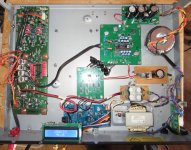
Below is my test bed. It consists of Triad Magnetics VPT48-520, Ryan's Cap multiplier, Nakamichi CDC-3A Power transformer and Regulator Circuitry, cheap spdif to I2S board, Ryan’s simultaneous board, D3, Nakamichi CDC-4A output stage. It actually sounds pretty decent!
This is temporary to make sure the boards I'm building work and a reference since this is probably as poor a quality component setup as can be done and improvements in power supplies and output stages can be made. The simultaneous board and D3 boards are the second ones I built. Both D3 boards exhibit the same behaviors as I have previously mentioned in this thread and both sound the same so the builds are good. I will now be able to experiment with different components while having the reference.
Mark K.
Attachments
What sort of VA rating is needed if using one transformer only to power the D3?
I know it's probably overkill, but I have several 12-0-12vac 1.5A EI core transformers. I figured using one of those without the CT. Should give 0-24vac if my fever isn't too bad lol
That is a bit on the high side, but the next step down that I have is single secondary 0-9vac so not really an option.
Ryan mentioned in Post #154 that the 26V needs to supply 140mA. Your 12-0-12VAC 1.5A transformer is more than adequate and will definitely work.
Ryan mentioned in Post #154 that the 26V needs to supply 140mA. Your 12-0-12VAC 1.5A transformer is more than adequate and will definitely work.
Yes, in that case one of the 4 - 5pcs of those transformers should do nicely, can't go wrong with a bit of overkill 😉
If the fever hasn't completely wrecked my brain yet, that makes them about 36VA.
I'll likely use an LT1083CP board for "pre-reg" as I think they are better than the LM317.
Thanks for the info 🙂
i would like to install d3 panel. panels ready. what to measure before hanging a 26v float? If I don't insert a tda chip in the d3 panel, how can I check the voltages? what is the current flowing across the power supply panel 15r during operation? (shunt plus tda chip)
I would recommend testing the power to the TDA1541A socket without the TDA chip installed. Check for +5V, -5V, and -15V. If all is good, then install the TDA chip.
I would not test with a pricey chip. I have a TDA1541 non-A chip that I use for testing. It is much cheaper than an A chip and would not be a big loss if it was damaged.
I would not test with a pricey chip. I have a TDA1541 non-A chip that I use for testing. It is much cheaper than an A chip and would not be a big loss if it was damaged.
Attachments
oh that's okay. just do not know shunt current plus tda currents how much. the floating power output is 34V without load. if tda chip is not in the socket, lm 317 is a lot of this tension. no?
You can check the specification sheets for the current requirements and put in dummy load resistors if you want to test under load .
I have tested without load.
I have tested without load.
QUOTE=ryanj;5558141]True, with the current of an extra 1541 to play with, it might be a winner.[/QUOTE]
Hello Mark,
Great job on your build. I would like to ask what is the voltage output on the ryan cap multiplier using the triad transformer? Im using a similar spec transformer 48vct and I’m getting 38 volts unloaded with my wall voltage at 125vac. I hope that it is safe when I load it with the dac board which requires 26v floating.
Id really appreciate your response.
Thank you
Hi Mayday,
Below is my test bed. It consists of Triad Magnetics VPT48-520, Ryan's Cap multiplier, Nakamichi CDC-3A Power transformer and Regulator Circuitry, cheap spdif to I2S board, Ryan’s simultaneous board, D3, Nakamichi CDC-4A output stage. It actually sounds pretty decent!
This is temporary to make sure the boards I'm building work and a reference since this is probably as poor a quality component setup as can be done and improvements in power supplies and output stages can be made. The simultaneous board and D3 boards are the second ones I built. Both D3 boards exhibit the same behaviors as I have previously mentioned in this thread and both sound the same so the builds are good. I will now be able to experiment with different components while having the reference.
Mark K.
Hello Mark,
Great job on your build. I would like to ask what is the voltage output on the ryan cap multiplier using the triad transformer? Im using a similar spec transformer 48vct and I’m getting 38 volts unloaded with my wall voltage at 125vac. I hope that it is safe when I load it with the dac board which requires 26v floating.
Id really appreciate your response.
Thank you
Hi tubo,
Thanks!
With approximately the same wall voltage as you I settled at 17.2 ohms for R4,5. This results in approximately 26.5Volts with D3 connected. I had found the 15R were going to feed too much voltage with my setup so I tried a 15R+2.2R in series to get 17.2R but you could try around 18 or more and work your way down to get the voltage you want. I think ryan said he ran the D3 on 27Volts on the high side and it worked.
Good luck,
Mark K.
I will say I used a 270ohm 3watt dummy load to first test the cap multiplier and work out a safe value for R4,5 to first power the D3. I believe it was 20ohm resistor in R4,5 but then when D3 was connected voltage was too low so I worked my way up to 26.5Volts by lowering the value of R4,5 to 17.2ohms.
Mark K.
Mark K.
Hi Greg,
Is your D3 running now? I hope it is after replacing the u.fl sockets.
Ben
Ben,
Thanks for asking. It did not. I had to order a new board from Ryan and I've been just too busy. But, I did do a test with air for the U.Fl male connectors,and had perfect success. So, when I get some some time after family stuff over the holidays I will populate the new board with air.
I bought both low temp paste and flux paste. Are you using flux or just paste?
Cheers, and thanks again for asking!
Merry Christmas,
Greg
I will say I used a 270ohm 3watt dummy load to first test the cap multiplier and work out a safe value for R4,5 to first power the D3. I believe it was 20ohm resistor in R4,5 but then when D3 was connected voltage was too low so I worked my way up to 26.5Volts by lowering the value of R4,5 to 17.2ohms.
Mark K.
Thank you Mark... Power supply is working and I got 25.8 volts on the cap multiplier.
Thanks again
- Home
- Group Buys
- DIY TDA1541A PCB "D3"