Well, motorboating is still there  🙁...
🙁...
I first disconnected completely one channel => no effect
Then I shorted one of the coils in each CM-choke (both that would join to make GND) => no effect
I also tried a higher current version of the chokes => no effect
Finally, I removed both CM-chokes of the channel in test and replaced it by a regular CRC => no effect... 😱
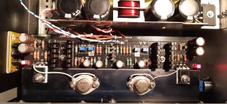
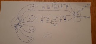
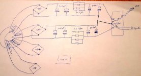
Attached some pictures, schematic and another sound file in the .zip.
All tests done with only one channel, the other one is disconnected after the bridges.
With everything I tested, it looks like it are the Vfet amps that are motorboating?! Know I have the same issue on both channels (see my long post earlier about a week ago..: Sony VFET Amplifier Part 2 )
🙁...I first disconnected completely one channel => no effect
Then I shorted one of the coils in each CM-choke (both that would join to make GND) => no effect
I also tried a higher current version of the chokes => no effect
Finally, I removed both CM-chokes of the channel in test and replaced it by a regular CRC => no effect... 😱
Attached some pictures, schematic and another sound file in the .zip.
All tests done with only one channel, the other one is disconnected after the bridges.
With everything I tested, it looks like it are the Vfet amps that are motorboating?! Know I have the same issue on both channels (see my long post earlier about a week ago..: Sony VFET Amplifier Part 2 )
Attachments
Last edited:
Wait a second, I recall something about TL431 instabilities. See https://www.diyaudio.com/forums/pass-labs/276711-sony-vfet-amplifier-2-a-368.html#post5601163 #3673
What is the exact part number of your TL431 and what values are the capacitors around them?
What is the exact part number of your TL431 and what values are the capacitors around them?
Perhaps it is a stupid observation, but can't be this motoboating because of those white leads, betweenMOSFETS and VFETS?
(You know, I know nothing about electronics, other than that, electrons will choose the easiest way to flow.)
At least, I don't have them in my amp.
Moreover I must have to say my Pass SONY VFET amps have the least noise, between all of my builds.
My PSU build almost the same, as yours, I think.
(You know, I know nothing about electronics, other than that, electrons will choose the easiest way to flow.)
At least, I don't have them in my amp.
Moreover I must have to say my Pass SONY VFET amps have the least noise, between all of my builds.
My PSU build almost the same, as yours, I think.
Wait a second, I recall something about TL431 instabilities. See https://www.diyaudio.com/forums/pass-labs/276711-sony-vfet-amplifier-2-a-368.html#post5601163 #3673
What is the exact part number of your TL431 and what values are the capacitors around them?
And, did you use the specified value caps in the Vfet build?
nash
Shots fired! 😀
Nope, I didn't. I used 470uF Panasonic FR caps iirc. My amp has been working flawlessly for over two years now.
Nope, I didn't. I used 470uF Panasonic FR caps iirc. My amp has been working flawlessly for over two years now.
Wait a second, I recall something about TL431 instabilities. See https://www.diyaudio.com/forums/pass-labs/276711-sony-vfet-amplifier-2-a-368.html#post5601163 #3673
What is the exact part number of your TL431 and what values are the capacitors around them?
😱 Oh noooo... Looked it up => still had my packing list from mouser, it is the TL431BILPR I used. Now I also do remember that while I was doing measurements, I found the Vref voltages a bit on the low side. Since others measured in a similar way, I did not pay more attention to it. Don't know if there is a link.
That would mean I need to go through the whole set-up procedure again for both amps.... I need more than one drink right now...
Really? Well, I would prefer this much more as a solution than the TL431B => TL431A!! I try it right away (drinks will have to wait for now)if that ends as not being TL431 issue, try this
Really? Well, I would prefer this much more as a solution than the TL431B => TL431A!! I try it right away (drinks will have to wait for now)
Time for a drink ... Next step really is replacing the TL431B's???
Attachments
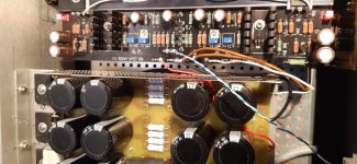
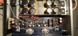
aren't those wires rather tiny for currents involved ?
OK - they probably aren't by older standards , but we are all used to make welder type of PSU nowadays ...... 🙂
OK - they probably aren't by older standards , but we are all used to make welder type of PSU nowadays ...... 🙂
Shots fired! 😀
Nope, I didn't. I used 470uF Panasonic FR caps iirc. My amp has been working flawlessly for over two years now.
Not sure what you mean by "shots fired"? I was only suggesting to Berny that the value of caps used matters especially with the TL431A. I meant no slight to you. Your comments have always be helpful to me.
nash
Well, motorboating is still there
I haven’t been following what you have done here so apologies if this has already been looked at.
Have you checked to make sure your rca connectors are properly isolated from the chassis?
This will definitely cause motorboating
Hallo everyone, thank you for the help and ideas... to cover suggestions & remarks:
Capacitor values and type have been respected: 47uF and 220uF, all Silmic II
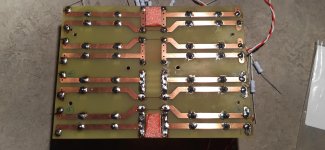
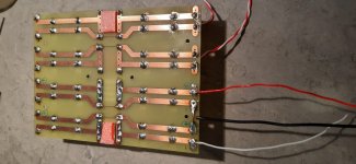
The white wires on top are silver plated copper in ptfe, prefered these over stainless steel screws and bolts as conductor. Sleep is better this way. I did cut the traces that became unnecessary to avoid loops.
Left and Right are fully split and grounds are not connected, RCA grounds are insulated from chassis and from each other. Anyway, the problem is still present with only one channel connected and iputs shorted.
So for now I suspect the tl431B I used. I will see if I can tame it by adding some capacitance, although I undestood from Nelson that we need to be carefull not to disrupt the way voltages come up at startup or currents could go wild...
Any other remarks welcome!
Capacitor values and type have been respected: 47uF and 220uF, all Silmic II
The white wires on top are silver plated copper in ptfe, prefered these over stainless steel screws and bolts as conductor. Sleep is better this way. I did cut the traces that became unnecessary to avoid loops.
Left and Right are fully split and grounds are not connected, RCA grounds are insulated from chassis and from each other. Anyway, the problem is still present with only one channel connected and iputs shorted.
So for now I suspect the tl431B I used. I will see if I can tame it by adding some capacitance, although I undestood from Nelson that we need to be carefull not to disrupt the way voltages come up at startup or currents could go wild...
Any other remarks welcome!
Isn't the TL431B just a tighter-spec part to the 'A'? I don't understand how that could cause issues....
What about the F4, BA-2 & 3? Has the 'B' part also been found to cause issues there?
What about the F4, BA-2 & 3? Has the 'B' part also been found to cause issues there?
I had an issue with one channel in my build, turned out to be a bad tl431, luckily I ordered extras. Replaced and been working flawlessly ever since.
From what I see in the TI data sheet, B is thighter spec'ed (probably reason why I took it), but appears slightly less stable... see Rodeodave comment & link.
Huh. I aways assumed they were the same part graded, but maybe the 'B' employs more feedback to get to the higher spec....
Long story short: it works!! (this time without the putputput)
longer story: it were indead the TL431B's... more precisely Q13 and Q14. I could tame it by putting only 100nF over R15 and R16 (reducing gain of the TL431). But as I'm not an expert, I preferred replacing them by other TL431's I had. I did not touch the other two (Q11 and Q12)
Looking for more info, I found this: Simple Voltage Regulators Chapter 2: Output Impedance
=> wouldn't adding these capacitors over R15 and R16 not be an overall improvement to do anyway?!
Thanks all for the support and specially Rodeodave for pointing me in the right direction!!
Somehow I believe more people might have oscillation issues, but are not aware.. My speakers are 93dB and I heard it by accident with my ear against the woofer. I have some scope images I can post later if anyone is interested...
Is there more than one schematic? In the version of the article I have Q13 and Q14 are the JFET cascodes (BJTs, not TL431s). 😕
Hi Jeff,
I think Berny is referring to the diyaudio project version (single pair vfets per channel):
http://www.firstwatt.com/pdf/art_diy_sony_vfet.pdf
There Q13 and Q14 are TL431 regulators.
Cheers,
Dennis
I think Berny is referring to the diyaudio project version (single pair vfets per channel):
http://www.firstwatt.com/pdf/art_diy_sony_vfet.pdf
There Q13 and Q14 are TL431 regulators.
Cheers,
Dennis
- Home
- Amplifiers
- Pass Labs
- Sony vFET Amplifier Part 2