An over damped system will take away natural decay from the signal, I was just wondering how damped of a system would that take.
So I am still fiddling with TM programmings, I've got the sens only slightly less than the ported design, box around 11cuft. and xmax at 14mm/115db(30hz)....so this would be vs a ported... since sealed cant get that loud without leaving xmax...The TL's xmax resembles that of a sealed so the lower you go the more it needs....ported is a few mm below xmax down to its tuning of ~20hz.....
It seems like with TL I can choose a system q depending on CSA size.....kind of cool, so I can have the system q of a sealed and extension of a sealed. And all of this trouble is worth it over a Ported? I'm not sure if dipole is going to be good for studio work.
Damping of a cone driver include the suspension (surround and spider), motor (voice coil and magnet circuit) and amplifier output resistance. An overdamped driver has less ripples in the freq. response at the price of a reduced low-frequency response.
I’m going to bring the efficiency down to match that of the sealed alignment. I sim’d a sealed enclosure at 6cuft, the qtc was 0.429....which would mean that it would be slightly more restricting than the sealed being that a TL has benefit of output at the terminus.
Last edited:
Unless you overstuff the TL 😉
In a compression driver the diaphragm (material) and possible foam in the rear chamber are the most obvious parts wrt damping of resonances. Besides, the viscosity in the air and thermal conductivity at the boundary also cause damping, which affects the vibroacoustic behaviour of the system.
In a compression driver the diaphragm (material) and possible foam in the rear chamber are the most obvious parts wrt damping of resonances. Besides, the viscosity in the air and thermal conductivity at the boundary also cause damping, which affects the vibroacoustic behaviour of the system.
JohnK has a paper on his site somewhere wherein he shows the math to demonstrate that a Q=1 filter gives the accurate amount of bass. It's surprising. Of course a woofer+box+baffle+room will raise the Q - making a woofer with a Q<1 desirable.
The contradictions in the title of that link made me smile. First wince, then smile. 🙄
The marketing isn't great on this driver but in the context of this thread it certainly could deliver good results with a little eq and woofer support below 300hz.
The PRV 5" doesn't measure as nice in the mid-range and treble but seems to work well on various non-optimized horn profiles.
I wonder if a slightly lower Q would make sense in light of a heavier cone. A Q=1 for an 18" probably isn't the same as a 4" driver?
without the perfect response pictured what does it all mean. The perfect impulse would have no decay or attenuation would it not?
without the perfect response pictured what does it all mean. The perfect impulse would have no decay or attenuation would it not?
Attachments
Last edited:
JohnK has a paper on his site somewhere wherein he shows the math to demonstrate that a Q=1 filter gives the accurate amount of bass. It's surprising. Of course a woofer+box+baffle+room will raise the Q - making a woofer with a Q<1 desirable.
Couldn't find the paper on his (now defunct) website.
Did find this quote though (in this thread):
"Transient response to what? If you are trying to reproduce bass accurately high frequency response is not particularly relevant. Damping as discussed above, is about how system, once disturbed, returns to its rest state (not steady state) once the signal is removed. One thing often over looked in these plots of impulse or step response is the effect of damping on amplitude response. For example, a critically damped system will have an amplitude response at its resonant frequency that is 1/2 that of the flat band amplitude. A slightly under damped system, Q = 0.707, Butterworth alignment, will have amplitude of .707 that of flat band, and a Q =1 will have and amplitude at resonance equal to that of flat band but with a small rise above flat band as resonance is approached from above. All of these system will have some small oscillation which dies out very quickly. But at the same time, consider a musical instrument such as a drum or bass. They are very under damped and will oscillate for an extended time naturally. Q of thes system could be as high as 50, 100 or more. Thus how significant is a low amplitude oscillation of an extra couple of cycles that is close to inaudible? Really to me is that what matters is the ability of the system to follow the input signal as accurately in amplitude as possible. To do that a Q somewhere beteeen -.7 and 1 is required. What is often missed is that when a signal is applied to a system, like music, the system is exhibiting a forced response. The value of Q will determine how well the system's forced response follows the input when the input contains frequencies close to resonance. Different values of Q will effect the amplitude and phase around resonance differently. Of course, when taking about damping and Q in this manor we are limiting the conversation to 2nd order alignments (sealed boxes)."
__________________
John k....
Suprising is that ESL57 with high Q at 100Hz gives very satisfactory bass and perfect blend unlike 15" in large BR at domestic levels.
It swings up, so it swings down. If it didn't average out to zero, the cone would shoot off into the next room.The perfect impulse would have no decay or attenuation would it not?
That - IIRC - sums it up well. If I can find the paper I'll link to it. Otherwise I might ask JohnK to post it.Couldn't find the paper on his (now defunct) website.
Did find this quote though (in this thread):
It swings up, so it swings down. If it didn't average out to zero, the cone would shoot off into the next room.
The perfect impulse, that which is identical to the source, in this case, is a Straight line, if I recall. So Q0.5 is the best looking. Right?
Last edited:
The perfect impulse, that which is identical to the source, in this case, is a Straight line, if I recall. So Q0.5 is the best looking. Right?
I'm a big believer in trying to achieve perfect impulse...….but there are some huge real world caveats ime/imo…
First, the straight line trace that doesn't go down from peak towards zero ...well it's for DC to Light bandwith...so throw that trace out. 🙂
Next, a Dirac pulse is as good as we can get imo...a single sample, 20-20kHz first sample of all frequencies contained in the pulse...
It will decay in a nice straight line from peak to zero.
(It's more doable in speakers than I think most folks believe is possible.)
Last, and this is the biggie to me...….
….looking at anything short of a 20-20kHz impulse is worthless, other than discerning time/phase issues between passbands.
IOW, looking at a sub's impulse is worse than worthless, given its narrow passband at the bottom of the spectrum where first sample contributions to a Dirac impulse are so very low in amplitude.
The definition of transient response is 100% the definition of magnitude and phase response.....20 to 20kHz….
As complicated as we try to make things...flat mag and flat phase 20-20k totally, completely, define a perfect impulse 😉
You're talking about the way the response deals with not going down to DC, as Mark also says. I think there are more effective ways to deal with rooms (at these frequencies) than looking at an impulse.So Q0.5 is the best looking. Right?
As complicated as we try to make things...flat mag and flat phase 20-20k totally, completely, define a perfect impulse
This does (unfortunatley) still leave room for discussions about the rolloff at both ends which will greatly influence the shape of the pulse. So we are back to camplo's question about which Q value is best ……..
Regards
Charles
This does (unfortunatley) still leave room for discussions about the rolloff at both ends which will greatly influence the shape of the pulse. So we are back to camplo's question about which Q value is best ……..
Regards
Charles
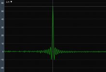
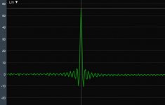
Hi Charles, here's why I can't see any value to using an impulse to determine which Q is best down low. Below are electrical impulses:
First full range, then high-passed at 39.3Hz at Q's of 0.5, 0.707, and 1.
It takes better eyes and discernment than mine to see any differences, not even between full range and high passed!
Bottom line imo, is that the bottom end of the spectrum contributes so little to an impulse plot, it's why bother looking.
Looking at bandwidth filtered impulse plots down low can help, but even then I find measurement programs have difficulty with repeatable measurements, or even finding consistent timings.
Given mag and phase are so much easier to discern, and the only things we can really adjust anyway...!!
...and are the components that end up making a good impulse/step when it's all said and done....
….well, I keep coming back to why bother with impulse other than to check it for confirmation of a good tuning.
But to each their own...just my 2 cents...
Attachments


Last edited:
What I would do and have done is build my sealed box for a high Qtc when trying to minimize size and a low Qtc to maximize efficiency per Hoffman's Iron Rule. In operation I shape the response with equalization, thus also tuning the Qtc. Even so, I would keep the untuned box Qtc between .5 and 1.25. At the low end, you don't want to eliminate the air spring the driver design may depend on. If raw Qtc is too high then so too may be power requirements. I'm sure all this is obvious but it may have been lost sight of in this discussion.
You can have any Qtc you want given enough EQ and amplifier power, at least until you bring the system into an untreated or inadequately treated room. For me any thought of choosing the roll off shape or Qtc that sounds best has always vanished when confronted with the room modes I've been forced to live with. That may not be the case in a professional setting. I would be interested to hear to what extent Qtc changes are audible within that range of .5 to 1.
You can have any Qtc you want given enough EQ and amplifier power, at least until you bring the system into an untreated or inadequately treated room. For me any thought of choosing the roll off shape or Qtc that sounds best has always vanished when confronted with the room modes I've been forced to live with. That may not be the case in a professional setting. I would be interested to hear to what extent Qtc changes are audible within that range of .5 to 1.
You are actually right regarding the usability of the pulse response since even an adventurous phase response can look quite good as pulse response (that's why I prefer the step-response).
OTOH your examples have pre- and post-ringing like I have never ever seen with a real life example.
Regards
Charles
OTOH your examples have pre- and post-ringing like I have never ever seen with a real life example.
Regards
Charles
Another quote by John K, which may interest camplo:
"If I have to design a dipole that will have high efficiency/sensitivity from 100 Hz up, frankly it's a no brainer. I say 100 Hz because I think most would agree than any sense of dynamics is coming from above 100 Hz, probably a lot higher.
Looking past that, about transient thermal compression, I think there should be easy ways to observe that by simple impulse testing. For example, start with a single impulse and make consecutive test, each time doubling the magnitude of the pulse. Then compare the measured impulse, it should double in amplitude and the FFT of the impulse should show the same frequency response with level increased nominally by 6dB. Next, since a single impulse would not reveal effects of lagging thermal response, make the same type of measurements but instead of a single impulse run a series of 2,3, 5,....N pulses closely spaced and look to see if there is any significant degradation between the first and last pulse as the level is increased. No degradation indicates no significant lagging thermal effects."
and:
"As I said previously, one of the things about high efficiency designs is permanent hearing damage. It does hurt, in the long term."
Last edited:
- Home
- Loudspeakers
- Multi-Way
- Is it possible to cover the whole spectrum, high SPL, low distortion with a 2-way?