Hello to everybody.
Son of a technician, I learnt how to solder when I was only seven years old. Then, I rerouted my live as a software man and only adventured myself in doing/repairing very simple and small circuits. So, I'm very rookie in building such big circuits as the one I'm describing here and will be very grateful for your help and advices. I really need this box and I'm always trying to find an excuse for returning to the past and learn some electronics, once and for all.
(Excuse my English too, if it's not as correct as it should be.)
GOAL:
To build a circuit with 2 functions:
+ Pre-Amplifier of electret microphones with output to the PC's microphone input.
+ Mixing and Amplifying of the PC's line output plus the microphones' signal, and sending them to a 32 ohms Headphones.
CHARACTERISTICS:
DESCRIPTION:
DOUBTS:
Thank you, very much.
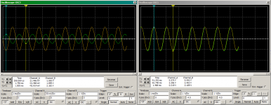
I have attached some screenshots and a zip file with the whole project (Spice netlist, images and the circuit file for MultiSim). The oscilloscopes image shows the final output signals (DC coupled) and the op-amps outputs before being mixed (DC coupled, shifted -4.5V).
Son of a technician, I learnt how to solder when I was only seven years old. Then, I rerouted my live as a software man and only adventured myself in doing/repairing very simple and small circuits. So, I'm very rookie in building such big circuits as the one I'm describing here and will be very grateful for your help and advices. I really need this box and I'm always trying to find an excuse for returning to the past and learn some electronics, once and for all.
(Excuse my English too, if it's not as correct as it should be.)
GOAL:
To build a circuit with 2 functions:
+ Pre-Amplifier of electret microphones with output to the PC's microphone input.
+ Mixing and Amplifying of the PC's line output plus the microphones' signal, and sending them to a 32 ohms Headphones.
CHARACTERISTICS:
- Preamplifier's output of about 20 mVpk (40 max) to be adjusted at setup time.
- Mixer/Headphones amplifier's output of about 1 Vpk, by a load of 32 ohms.
(Actually, I'd wish to be able to connect 2 headphones, eventually, so I'm thinking of putting 2 jacks connectors in series to avoid the voltage dropping). - I don't care whether the initial adjustment of the trimmer R11 affects the amplitude of the input to the mixer/amplifier. What I must avoid is that the adjustment of the volume potentiometers (R3,R15) affects the microphone's output. Due to that, I must isolate these two stages by means of a Buffer (U1A).
- Although I don't want bad sound in the headphones, the HIGHEST priority of the circuit is the good output of the microphones to the PC's sound card, for recording. Here I need the best amplification with the minimum noise.
- I must avoid to a maximum the cross-feed between the 2 channels of the microphones, because the main reason for building this circuit is to replace the horrible recording/monitoring features of my new motherboard's sound card in an application for directional localization of sounds. For the same reason, I should also avoid the cross-feeding between the two output channels to the headphones while I am monitoring or listening to the recorded audio.
DESCRIPTION:
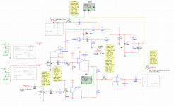
- The circuit is split into two stages. The first one is an electret microphone Pre-Amplifier with the output MIC_OUTPUT (top of the diagram). The second stage is a Mixer/Amplifier of the first stage and the line input LINE_INPUT, for driving a 32 ohms Headphone.
- The circuit will be fed by an external power supply of +9V. For simplicity, instead of using a supply splitter (virtual ground) for the op-amps, I'm using a Reference-Voltage of 4.5V.
- In order to keep the amplified noise to a minimum, for the first stage I'm using a transistor instead of an op-amp.
- To isolate the impedance between stages, I'm using one half of the op-amp (U1A) as a Buffer.
- To be able to present a low impedance to the low load of the headphones, I'm also using one half of another op-amp (U2B) as an output buffer.
- In the first stage, R20 keeps under 7V the voltage applied to the electret microphone (the maximun uses to be 10V in most of the datasheets I've read).
- To simulate the electret microphone, I'm using an AC Current signal generator of 1uA and to simulate the sound card's line output I'm using a AC Voltage signal generator of 0.4V.
- The variable resistor (trimmer) R11 is soldered to the PCB and will be used to adjust the microphones' sensibility at setup time. After that, it will remain fixed.
- The Volume potentiometers R3 and R15 are dual audio-logarithmics, external to the PCB. Maybe I'll replace them by linear ones with a resistor, in order to simulate the exponential curve.
- For simplicity, I'm not using neither an active mixer nor a panner to mix the microphone and the line outputs. I could add, instead, a global volume by means of a potentiometer to ground, just before the output buffer.
- With the same configuration as in the image, I'm getting in the simulation values of 21 mVpk at the microphone output and 1.1 Vpk (24 mA rms) at the headphones output.
- The circuit depicts a single channel. Both channels will share the same power supply but no any other element, save the dual volume potentiometers (R3,R15) and the stereo jacks.
- Still to be implemented, there will be a Led and a Switch between the power supply and the circuit.
DOUBTS:
- Will it even work?
- What are the correct values for the resistors (R1,R2) and capacitors (C1,C4) at the Reference-Voltage output? ¿May they be electrolytic ones or should they be Film (polyester) ones? I haven't found any examples for voltage reference, but for supply splitters only.
- If I simulate the electret microphone with an AC Current source, everything is fine but if I simulate it with a JFET transistor, all the signals drop near to ground. Why?
- At the Microphone output and at the Headphones output, I'm putting resistors (R6,R7) in order to simulate the impedance of the sound card and the headphones. Although all those external elements will be connected most of the time, should I put some real resistors there, in case some of those elements are disconnected from the circuit? May be 5K and 500 ohms resistors?
In the case of the headphones, it's really simple because I can put a 32 ohms resistor between the detection pins of the jack connector. But the output from the microphone preamplifier will be a soldered cable, in order to minimize noise. - To avoid the crossfeeding between the 2 channels of the microphones, I'm avoiding the use of the same dual op-amp for different channels. So, the buffer at the end of the preamplifier and the main microphone amplifier are both one half of the same op-amp (U1A, U1B). There will be any problem for doing the same with the line amplifier and the buffer to the headphones (U2A, U2B)? Would it be better to use the same op-amp for both amplifiers and the same op-amp for both buffers?
- The capacitors C5,C6,C8,C10, should they be electrolytic, film type, or ceramic ones (at least for C5)?
Thank you, very much.
I have attached some screenshots and a zip file with the whole project (Spice netlist, images and the circuit file for MultiSim). The oscilloscopes image shows the final output signals (DC coupled) and the op-amps outputs before being mixed (DC coupled, shifted -4.5V).
Attachments

Humm. I think I'm watching a big mistake here.
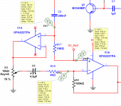
The first buffer (U1A) is AC coupled to the preamp by C2 but, because the power supply in not giving negative voltages, this op-amp should be clipping the output signal. But it's not! The simulation depicts a shift of aprox. +1 volt DC in the input and, because of that, it is working.
Is it possible or Is this a bug in the simulator?
Shouldn't I feed the non-inverting input of U1A with DC_Ref too?
Humm. I think I'm watching a big mistake here.
The first buffer (U1A) is AC coupled to the preamp by C2 but, because the power supply in not giving negative voltages, this op-amp should be clipping the output signal. But it's not! The simulation depicts a shift of aprox. +1 volt DC in the input and, because of that, it is working.
Is it possible or Is this a bug in the simulator?
Shouldn't I feed the non-inverting input of U1A with DC_Ref too?
Where are the other inputs to the opamps connected ... I see "DC_Ref" which is a voltage divider and filter that bisects the power supply... correctly biasing the inputs to the chips.
But the input of U1A is not connected to DC_Ref. Why the output signal is not clipped then? It seems to be because its input signal is shifted by +1V DC. The capacitor C2 is supposed to prevent that shift. Isn't it?
But the input of U1A is not connected to DC_Ref. Why the output signal is not clipped then? It seems to be because its input signal is shifted by +1V DC. The capacitor C2 is supposed to prevent that shift. Isn't it?
Good catch... I see it now, and yes it should be on DC_Ref through a resistor.
Thank you, Douglas, for your input.
Do you have some more advises? I suspect I have lot of things wrong there.
Do you have some more advises? I suspect I have lot of things wrong there.
Well. I think I have now correctly biased the Buffer U1A.
- I have connected its non-inverting input to DC_REF (+4.5V) through R17.
- I had to increase C2 value to 200nf for a good response at 100Hz.
- Output signals keep almost the same.
Attachments
Well. I think I have now correctly biased the Buffer U1A.
Have I done it right?
- I have connected its non-inverting input to DC_REF (+4.5V) through R17.
- I had to increase C2 value to 200nf for a good response at 100Hz.
- Output signals keep almost the same.
Since you are still in simulations you should toy with the value of R17. You might find that a higher value (47k?) will give you better frequency response without a big increase in noise.
Also looking at your first schematics... I would increase c8 and c10 substantially, unless you deliberately want it to lack bass response on the line input. Try 10uf. To get reliable 20 to 20k response you want your low frequency roll offs to start at about 5hz or so.
Last edited:
Thank you, very much.
I think I was simulating at 200Hz when I chose that capacitors.
I'll give your numbers a try. Thanks again.
I think I was simulating at 200Hz when I chose that capacitors.
I'll give your numbers a try. Thanks again.
Note that many op-amp models do not model the supply pins nor their relationship to the signal path. Usually they simply model a current from +V to -V.
Yes, thank you Steve. I'm aware of such limits of the simulation. That's why I don't trust when it says that my circuit works fine. So long, the numbers for the capacitors that Douglas gave me are working well but I need to adjust some others, because I was doing the simulation for 100 Hz as the minimum and I see that all the signals drops dramatically when I go below of that.
My comments: Biasing a transistor like that is bad practice - transistor gain is not a well behaved parameter, you should not be relying on it. Use a resistor-divider to bias the base voltage and emitter degeneration to set the standing current and the gain. A low-noise transistor is the best choice here.
The summing point is via 200 ohm resistors, meaning the two opamps are each driving a low impedance reactive load - change those to 2k resistors to avoid overloading the opamps.
And lastly I can't help feeling that there are more opamps than needed.
The summing point is via 200 ohm resistors, meaning the two opamps are each driving a low impedance reactive load - change those to 2k resistors to avoid overloading the opamps.
And lastly I can't help feeling that there are more opamps than needed.
Thank you, Mark.
I've changed the resistors at the summing point.
I'm still tuning the capacitors. Signals are decaying a bit.
I think I understand what you mean about the transistor. I didn't know that. But I don't know whether I know how to do it. I'll do a bit more research about this.
I appreciate a lot the help of all of you.
Thank you, very much.
I think I was simulating at 200Hz when I chose that capacitors.
I'll give your numbers a try. Thanks again.
When working on low end roll off, I generally simulate at about 3 or 4 hz. Also doing FFT (AC-frequency scan) simulations is very helpful.
But, when you go that low in frequency you let the signal to drop a bit, don't you? I mean, to drop a 10 or 15 percent? I had to change almost all the capacitors and some resistors after your replay and can't avoid the signal to drop a bit, running the simulation at 20Hz.
@ Mark Tillotson
Mark, I see that I didn't understand your reply enough.
I understand what you say about using the voltage divider for the biasing but I don't understand the emiter degeneration concept in order to vary the gain. ¿Could you be more specific about that?
Regarding the number of op-amps (I misread it as 'there are a lot of better op-amps in the market') I think I need 2 of them as amplifiers and two more to act as buffers; the first one because when I move the volume potentiometer, the impedance of the circuit varies and so does the signal in the microphone output of the preamplifier. I need to avoid this.
The second buffer is there to be able to drive the very low impedance of the headphones (32 ohms). I thought both buffers were necessary. Please, tell me if I'm wrong.
Thank you.
Modifications 02 - Capacitors and Resistors values.
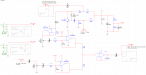
These are the changes made to the values of some capacitors and resistors, following your advices:
The value of these capacitors were drastically increased, to minimize the cut-off at 20Hz:
C2, C3, C5, C6, C8, C10
All of them are now polarized (electrolytic or film types?).
The values of these resistors, at the mixing point, were drastically increased, to not overload the op-amps:
R18 and R19
Signals at the outputs remain the same above 1KHz but are drastically improved in the range of 20 to 100Hz.
I'm still studying the advices from Mark Tillotson about the biasing of the transistor.
But it's past time to go to bed here, in the Canaries...
Attached you have the new images and circuit files.
Attachments
Last edited:
But, when you go that low in frequency you let the signal to drop a bit, don't you? I mean, to drop a 10 or 15 percent? I had to change almost all the capacitors and some resistors after your replay and can't avoid the signal to drop a bit, running the simulation at 20Hz.
Does your software allow you to do FFT (spectrum) analysis? Simulating at a single frequency is seldom very revealing. if it doesn't you should look into new simulation software ... I use LTSpice which is free.
Capacitors roll off at about 6db per octave so if you are seeing a drop in response at 20hz it has probably started at 40hz (one octave up). This is why we design for 5hz or less. If we are down 6db or less at 5hz we will be at full output by 20hz.
@ Douglas Blake:
Thank you for the smart trick and its explanation.
Regarding the FFT analysis, yes it has this feature but I've been there for one hour, trying to figure out how to set it up and it's being hard. I think I will still doing it by analyzing at the low end and middle frequencies until I learn how to use it.
I don't want to abuse of your kindness but, in case you have some spare time, could you answer some of the doubts I have in the list at the original post? I'd be very grateful if you can.
I'm concerned, because I feel like either I start buying the components this Monday or I would abandon the project for ever, because it has taken one month, at almost full time, since I started it. Of course, I'm learning a lot but I need the circuit just now or I'll have to buy some commercial sound box which I don't know whether it will fulfill my needs.
Thank you.
I don't want to abuse of your kindness but, in case you have some spare time, could you answer some of the doubts I have in the list at the original post? I'd be very grateful if you can.
First, if you are up against a time limit, which you say is Monday... be aware there is no way you're going to be ready. Simulations are not circuit design. They are a way to test the feasibility of a circuit design. You cannot reasonably expect to go directly from the computer screen to a fully functional device. Before a device is trustworthy it will need prototyping, testing and adjustments, perhaps even partial or full redesigns.
the main reason for building this circuit is to replace the horrible recording/monitoring features of my new motherboard's sound card
This I think is your real problem.
First you should know that Windows OS includes a very comprehensive monitoring system for any input... mic, line in, etc. that can be listened to on the speakers or a headphone. It also includes mic-boost on the microphone input up to 20db, and often at very low distortion. I would suggest that you thoroughly explore your sound setup panels... the function you are looking for is the "Listen to this device" checkbox, which will place sliders on your on-screen mixer for adjusting the levels.
The second bugaboo is that most PC microphone inputs do not support stereo. For that you have to use the Line In jack which does not have the commensurate mic-boost functions to allow you to control sensitivity.
Finally ... look at the sample rates for each device. Upping the sample rates and bits per sample can bring stunning improvements in sound quality.
Linux and BST also have similar features, but I am far less familiar with their setup and use.
To get better-than-soundcard results, even with your project, the only real answer is to go to a USB device, which bypasses the sound chip entirely. Here you can have anything up to and including a full studio console. There are plenty of inexpensive devices available for this task, all you need to do is pick one that gives you the features you want.
Now please don't take this wrongly ...
I am not saying your design is a failure, it might actually be bloody perfect, but I doubt you can know that by Monday.
I am also not trying to discourage you from DIY projects. In fact the opposite. I will strongly encourage you to continue with this hobby, IMO it's the best hobby of all. Your first project isn't bad, although there are still a number of issues that need addressing. I would encourage you to continue with it, but first spend some time studying up on theory and electronics in general. There is a link in my signature that will get you started down the right path...
- Home
- Amplifiers
- Chip Amps
- Sound Box design - Please, help.