Here is APEX A14 Layout files for DIY, it needs PSU60 for supplay OPAMP, VAS&Diamond Buffer and 2xEmitter Follower.
Any link to psu60
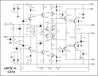
Q10 BD139 needs to be mounted on one of the output devices using the same bolt via short wires.
Thanks for the reminder. I see it now, printed on the board! Q10 has been moved. Bias tracks better now. It was creeping up quite a bit before mounting Q10 correctly.🙂
APEX AA11
Thanks Prasi for AA11. Please can u post PCB layout in PDF format.
Regard
Gurpreet
Last edited:
Only on/off function. You should add another relay and delay circuit for soft start. My 2 cents.
Thanks amigo...😀
Thanks Prasi for AA11. Please can u post PCB layout in PDF format.
Regard
Gurpreet
here are lay file and pdfs.
Attachments
what are they to be used for?hi all, is there any alternative to bc550 and bc560 for same quality
easy to find alternative would be bc546 and bc556 with same pins.
or you could use 2n5551 and 2n5401 but they have different pins,you just have to rotate these 180 degrees in relation to bc550-560
hi mile
Do you have pcb layout?
No, but alexmm made pcb for A23 and this pcb can be easy redesign to AF20 pcb.
hi all, is there any alternative to bc550 and bc560 for same quality
2N3904 2N3906 ...
here are lay file and pdfs.
Thanks Prasi, I will try with this layout.
One quick question regarding the heat sink size for the AX14 amp. I am using a small size cabinet with the heat sink size being 24.5cm(depth)/11cm(height)/2cm (fins width) and with the bias around -4mV to -10mV its very hot to touch. Some issue with my bias setting or the heat sink size is smaller??
I am checking the bias with the DMM's red wire being on the Q17 mosfet pin and the black wire being on the Output pin. Also I am using a 30+30v transformer secondary as rated below, 4 secondaries.
0-30v @ 2.5A
0-30v @ 2.5A
0-30v @ 2.5A
0-30v @ 2.5A
through the CRC psu which gives a stable +/-47VDC. I hope the voltages are fine for this amp.
Thanks
Last edited:
I asked several times PCB pdf for this PSU,No answer😕Any link to psu60
2N3904 2N3906 ...
for diy audio use: mj15024/mj15025 Motorolla original is beter or mj115024/mj15025 ON original mexico? wich one is the best ..i have both...however they are very very expensive in my contry...and fake is very much.
Last edited:

you are in new schematic's
Only upgrade and redesign old schematic.
- Home
- Amplifiers
- Solid State
- 100W Ultimate Fidelity Amplifier