In the interim - I have researched U1 - the Toshiba TA7313P.
It seems I can get them on e-Bay for a reasonable price. From what I've gathered, replacing that little bugger may be the next logical step.
I can't make heads or tails of how to test the part in situ. Is that possible / practical?
Actually that was my next suggestion. I've attached the datasheet.
First try the test with the speaker I described... it's entirely possible the amplifier is working and the protection circuit is blocking it.
A few things to check on the TA3717...
Pin 6 is your relay drive... it should be nearly 0 volts when the relay is energized. The easiest place to check this is probably right at the relay coil or on the cathode of D403. If this pin is low, the amp is not in protection. If it is high we need to dig a little deeper.
Other possibilities are that R417 is burnt. If it was you would see 0 volts on both sides of the relay coil.
In the event that pin 6 of the protection chip is not low, we would need to investigate it's inputs to see which one is triggering protection and why.
Attachments
Last edited:
Given that the service manual does not specify the bulk voltages, I'm going out on a limb so say they look alright.
Moving in the right direction, thank you!
Discoloration like that is a sign of heat.... rather a lot of heat actually. Something pretty bad happened there.
I would take that board out... <SNIP>
Interesting. I just assumed liquid. Wow, yeah, heat was spread out over the area. I'm having a tough time imagining what would get the board that hot.
All noted with thanks. I will get to that tomorrow. Once again, thank you!
Actually that was my next suggestion. I've attached the datasheet.
First try the test with the speaker I described... it's entirely possible the amplifier is working and the protection circuit is blocking it.
A few things to check...
Pin 6 is your relay drive... it should be nearly 0 volts when the relay is energized. The easiest place to check this is probably right at the relay coil or on the cathode of D403. If this pin is low, the amp is not in protection. If it is high we need to dig a little deeper.
Other possibilities are that R417 is burnt. If it was you would see 0 volts on both sides of the relay coil.
In the event that pin 6 of the protection chip is not low, we would need to investigate it's inputs to see which one is triggering protection and why.
Apologies. We seem to reply around the same time, and somehow I completely missed your speaker recommendation in the edit.
EDIT: There is a quick trick you can use to test everything but that relay... Set the amp up with inputs at a very low level ... this is not a full power test... Using a speaker you don't care about, hook one side to the speaker negative posts and using an alligator clip with a piece of stiff wire as a probe touch the other side to the amplifier output leads (Lout and Rout on the schematic) at the relay inputs... Do you hear music?
If you do, then the problem is clearly in the protection circuits which are on the power supply board.
I have been searching for a good spot on the boards for Lout and Rout. My guess is that they are two pins of the Relay. Currently, I think the only option is on the back of the PCB, but I am not sure. J7 is easily accessible and essentially is just four wires running from the PCB directly to the speaker terminals.
I have to pause for the evening, but I'll get to it with fresh eyes in the morning.
Thank you!
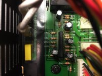
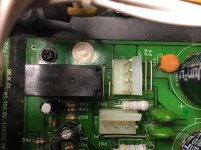
Pics attached of J7 / Relay area and TOSHIBA TA7313P area.
Attachments
I have been searching for a good spot on the boards for Lout and Rout. My guess is that they are two pins of the Relay.
Yes they are.
You can access them directly from the relay itself or from Pin 3 of J3 (left) and pin 3 of J5(right). Just push a probe (or stiff wire) into the plug next to the pin. The manual says it's a brown wire... should give you what you need to know.
Pics attached of J7 / Relay area and TOSHIBA TA7313P area.
It's a bit hard to tell from the photo but it looks like there might have been some heat/liquid damage in that part of the board as well.
Last edited:
Yes they are.
You can access them directly from the relay itself or from Pin 3 of J3 (left) and pin 3 of J5(right). Just push a probe (or stiff wire) into the plug next to the pin. The manual says it's a brown wire... should give you what you need to know.
It's a bit hard to tell from the photo but it looks like there might have been some heat/liquid damage in that part of the board as well.
I should have looked across the schematic. Sheesh... There needs to be a "facepalm" emoji. Anyway, thank you for pointing out the far easier method for accessing those points, I think I can safely rig something.
Nothing about this amp was/is pretty. I believe it had been in a very smoky environment. I cleaned it, but it needs a much better scrubbing.
I should have looked across the schematic. Sheesh... There needs to be a "facepalm" emoji. Anyway, thank you for pointing out the far easier method for accessing those points, I think I can safely rig something.
Well... we won't catch you on that one again, will we?
")
Nothing about this amp was/is pretty. I believe it had been in a very smoky environment. I cleaned it, but it needs a much better scrubbing.
You might want to make some inquries about its history...
It could provide some clues as to how it ended up as it is.
TA3717 are not real prone to failure. At 8 years or older, C413, C414, C415, C416, & C417 are highly likely to fail. If the amp is NOT putting out DC (test input of resistors R407 R408 for voltage below 200 mvDC to speaker ground) and the speaker relay will NOT pick up, I would replace those much before replacing any IC. Easier to do, too, IC's are tricky to desolder & resolder without damaging the board. Unless they are socketed. If U1 is socketed, with power off remove & replace. Oxide can grow on the pins & block low level signals going in. Pry IC out gently with bent tip pick, evenly on 2 ends so pins don't bend.
Regular USA distributors won't touch Toshiba parts, in my experience, and any you found on ebay/alibaba/amazon are likely beautiful counterfeits.
Little caps like this, I buy the 10000 hour service life grade so I don't have to do this again in 2 years. Digikey & Newark will show you the service life in the selector table if you ask for it. Mouser makes you link to each datasheet and look it up for yourself. Alliedelec only stocks 1000 hour parts. Never used Arrow, delivery would be too long from the west coast.
The .47 & 4.7 uf parts I would substitute ceramic disk caps at those voltages. Although a 4.7 may be $4, you may want electrolytic for that. I pay the premium I hate rubber caps so badly. I wouldn't buy 16 v parts, I'd buy 25 so I could keep a few for stock and use them elsewhere. Haven't had trouble with those so far, even using for 3 v electrolytic caps.
Last edited:
IC's are tricky to desolder & resolder without damaging the board.
Excellent advice!
For the above... solder wick and a solder sucker work wonders.
@indianajo - thank you so much for the additional advice.
Even if none of the caps prove to be faulty (today), I'll replace all that you've recommended. That particular board needs to be removed again anyway, so what's a little extra solder work among friends.
Douglas - Definitely. For good or for ill, I've become reasonably proficient with both.
Even if none of the caps prove to be faulty (today), I'll replace all that you've recommended. That particular board needs to be removed again anyway, so what's a little extra solder work among friends.
Douglas - Definitely. For good or for ill, I've become reasonably proficient with both.
Take the measurement before blindly replacing stuff! 20% of replacements go bad in the beginning. Replace DC detect parts ONLY if there is no DC condition causing the detect circuit to prevent relay closure. The end or R407 R408 facing the input connector is a great place to measure the voltage on speaker for DC. If voltage on speaker is in spec, and protection circuit is hanging the protection relay open, then you know something is wrong in the protection circuit. Then usual suspects method (old ecaps or oxide on connectors/pots) become economic.@indianajo - thank you so much for the additional advice.
Even if none of the caps prove to be faulty (today), I'll replace all that you've recommended. That particular board needs to be removed again anyway, so what's a little extra solder work among friends.
I'm of the opinion that meters do not detect bad e-caps. I bought the Peak $120 ESR meter, and nearly none of the caps that come out of old systems that **** out after being on for 10-30 minutes, fail. Current leakage at rated voltage and elevated temperature may show some correlation, but that measurement cannot economically be done. 2 volt tests at room temperature do not usually pinpoint the bad caps.
Just did a 8 year old HDTV converter that was hanging up after 20 minutes. 100% new e-caps, 100% great performance. Old caps in the bag don't read that bad.
Last edited:
I managed to sneak a bit of time.
------------
From Douglas - "Set the amp up with inputs at a very low level ... this is not a full power test... Using a speaker you don't care about, hook one side to the speaker negative posts and using an alligator clip with a piece of stiff wire as a probe touch the other side to the amplifier output leads (Lout and Rout on the schematic) at the relay inputs... Do you hear music?
If you do, then the problem is clearly in the protection circuits which are on the power supply board."
-------------
I followed these instructions, and my instincts tell me that I did it properly / as advised.
No music from either channel. Rats! So clearly even if the protection circuit / relay is still an issue - there seems to be something else amiss in addition.
Once again, assistance is greatly appreciated. I'm enjoying doing this, but I am not an engineer, nor a technician.
For those willing to dedicate the time, I am more than grateful, and will learn alongside during the process, but I fully understand if you guys need to cut bait. I'm game for continuing as long as it's fun or rewarding for you guys to help a noob along.
I managed to sneak a bit of time.
------------
From Douglas - "Set the amp up with inputs at a very low level ... this is not a full power test... Using a speaker you don't care about, hook one side to the speaker negative posts and using an alligator clip with a piece of stiff wire as a probe touch the other side to the amplifier output leads (Lout and Rout on the schematic) at the relay inputs... Do you hear music?
If you do, then the problem is clearly in the protection circuits which are on the power supply board."
-------------
I followed these instructions, and my instincts tell me that I did it properly / as advised.
No music from either channel. Rats! So clearly even if the protection circuit / relay is still an issue - there seems to be something else amiss in addition.
So it would seem...
Follow the cables you probed back to each amplifier and test at that end...
More stuff to check...
The opamps on the driver board use +15 and -15. This voltage originates in the power supply at Z1 and Z2, on the schematic. you can check it in stages from the end of r401 and r402 ... from there it goes to pin 3 and 4 on both J4 and J5 ... probe it there then follow the cables to the amp driver boards and see if it's making it to the other end. We can worry about the rest of the amplifier diagnostic later.
Now for that protection circuit...
Check the voltage on both sides of the relay coil. You can probe both sides of D403 for this what do you get?
While you're there... unplug the amp and using the continuity or ohms scale on your meter connect to both sides of D403 and make sure it's not shorted. (Note: Because this diode is directly across the relay coil, you may have to unsolder one end to get a good reading)
If all that is right... In the next step we get to probe the input pins on that protection chip to see which condition is not being met..
Last edited:
Because this was moving a bit quickly (for me) - I wanted to compile a quick summary and back up to make sure I did not miss anything.
This morning, I did the following -
"I would take that board out, clean it with rubbing alcohol, let it dry, flip it over and resolder all the connections. Just touch them with your iron to get them liquid and add a tiny bit of resin core solder (I prefer Kester 63/37, lead/tin) to make sure this whole thing isn't just a bad solder joint"
"For those corroded resistor leads I would check the points underneath --amplifier unplugged, ohms scale, right across it's legs-- to be sure the resistor wasn't open then brush them down, apply resin paste on the leads and tin them to prevent further corrosion."
I wasn't sure if the measurement for that resistor (R401) was to be done with the board fully removed and connected to nothing or in the amp fully assembled with all connections in place. With the amp fully assembled and all components in place - the value swings quite a bit (maybe as caps drain??) from about 660ohms down to settling in the 410ohm range. I forgot to do so, but I'll tin the legs later.
I had high hopes, and then they were dashed. After touching up the solder and re-assembly, I went through the original set of checks.
New observation - upon initial power up the protection LEDs lit. I thought I was on to something...
I decided to go through the initial set of checks again, and got:
~280mV across R417. That was new. Previously there was 0V
I checked the offset again using the inductors along with checking to see if there was voltage to the collectors. All good.
I then powered down the amp to do the quick and dirty speaker test. When I powered the amp back up... no protection LEDs. They had been lit moments prior. But, perhaps more importantly, when I tried the quick and dirty speaker test... MUSIC! Both channels.
So, I checked the voltage across R417 again... Nada.
Also, I think found the source of the heat in the discolored section of the board. R401 and R402 got very hot to the touch. I know this can be common, but they're very toasty.
I checked the voltages across the other 2W resistors for my own knowledge - R401: 28V and R402 = 28V R406 = 2V0.
So, progress that I am proud of, but now it seems the tide has turned toward the protection circuit as the most likely culprit. Maybe?
I think we were going down the path of diagnosis with no music from the quick and dirty check. Now, perhaps a new direction now that I have music from the quick check?
As always, thank you to all that have assisted. I'm learning quite a bit.
Nothing wrong with gentle cleaning with dilute alcohol.
I'm not sure what voltage r417 should have, the relay coil should get 12 to allow music flow if that is the rated relay coil voltage. If 5 volt coil, 5 v allows music, etc.
Usually when a direct coupled transistor amp stops performing, especially if the protection light is on, step 3 is measure DC at the speaker terminals < 200 mv. Step 1 & 2 were check power cord is plugged in & fuse okay, but if any lamps are on, you can count those as done.
Since there is a protection relay, one moves on to step 4 measure DC going into the protection relay. Since those terminals are hard to spot, I found 2 resistors that connect to them in post 27. Edit R407 & R408. With leads, the sides of those resistors going to the input jack should be easy to measure with the power on.
If both inputs are <200 mvdc to speaker return, then the protection circuit has a fault. Likely at this point bad e-caps. More data could be taken but the appropriate voltages are not shown in the print. My self, I'd start changing e-caps listed in post 27. Especially as the amp showed the typical "worked okay for 20 minutes after power on, then the okay time got shorter and shorter" dried up e-cap symptom.
Also the relay you installed, there might have been a mistake, which was the point of measuring power off the relay input for some hundreds of ohms across the coil, and a lower reading, usually 400 to 700 backwards, which means the diode is conducting.
Later if "no" dc to protection relay, power supplies okay (you checked rail voltage already +-44, check) and no music flows through the amp, more data can be taken. I trace music from input jack on with a Simpson 266 analog meter on 20 vac scale, then 2.5 vac scale. .47 uf capacitor is in negative clip lead to speaker ground to prevent meter response on DC. Digital DVM can't do this, they average signal over some seconds, besides most of them produce random numbers on music. Some people prefer a $$$ scope. Some people prefer a sound probe. I use a battery transistor radio set to put out ~1.7 vac on earphone jack to exercise amps. Cheaper than a frequency generator, and if set to rock music, the beats several times a second make the pointer jump in a way that no RF oscillation will do.
Last edited:
I then powered down the amp to do the quick and dirty speaker test. When I powered the amp back up... no protection LEDs. They had been lit moments prior. But, perhaps more importantly, when I tried the quick and dirty speaker test... MUSIC! Both channels.
So, I checked the voltage across R417 again... Nada.
This tells us two very important things ...
The amplifiers do work
and it is still being held in protection mode.
Basically we most likely have a fault in the circuit designed to detect faults.
Also, I think found the source of the heat in the discolored section of the board. R401 and R402 got very hot to the touch. I know this can be common, but they're very toasty.
I checked the voltages across the other 2W resistors for my own knowledge - R401: 28V and R402 = 28V R406 = 2V0.
The voltage across the resistors is less important than the voltage between the resistors and ground. Take a look at where R401 and R402 are in the circuit. That's a zener voltage regulator... basically the zener diodes form a divider with the resistor, creating a fixed voltage at the junction of the diode and the resistor ... Plus and Minus 15volts in this case... that's what we're looking to discover... is that voltage correct? It has to be because it is powering the op-amps in the driver board.
It's crappy design, a pair of 3 pin regulator chips would have cost less and worked better ... but it is what it is.
If the resistor fails... the voltage goes to 0, the amp shuts down and hopefully goes into protection. But, if the zener diode fails, the voltage goes to the bulk supply of about 40 volts which would destroy the op-amps on the driver boards. Thus it is far better to let those resistors get a bit toasty and let them fail rather than frying the driver boards. It's an engineering decision based on the lesser of two evils.
So before going much further I would measure from R401 and R402 to ground... on one side of each you should get ~40v on the other you should get 15 volts... which is correct. Moreover, given that the amplifiers both work, I suspect you will find it is correct.
So, progress that I am proud of, but now it seems the tide has turned toward the protection circuit as the most likely culprit. Maybe?
I think we were going down the path of diagnosis with no music from the quick and dirty check. Now, perhaps a new direction now that I have music from the quick check?
As always, thank you to all that have assisted. I'm learning quite a bit.
Yep, since you got sound from both amps we can now spend our efforts entirely on the power supply board and mostly on that relay and the ta3717 protection chip.
(FWIW ... The general process when you get an amp in protection like this is to first verify the power supplies are correct then check for DC offsets on the amplifier outputs before launching into wide ranging diagnosis. What you find there, tells you where to look next. This would take an experienced technician about 10 minutes. This being your first time through, time is not an issue. But I'm betting next time you knock this initial check off in no time at all.)
So next step... lets verify that the relay is not being told to energize... Lets follow the chain of R416, R417 and D403 ... If the circuit is trying to energize the relay you should get bulk voltage going into R416, something less going into R417, about 12 volts on one side of D403 and nearly 0 on the other side... If it is not trying to pull the relay in, you will get nearly the bulk supply all along that chain. So lets see what we get from that...
Nothing wrong with gentle cleaning with dilute alcohol.
I'm not sure what voltage r417 should have, the relay coil should get 12 to allow music flow if that is the rated relay coil voltage. If 5 volt coil, 5 v allows music, etc.
Usually when a direct coupled transistor amp stops performing, especially if the protection light is on, step 3 is measure DC at the speaker terminals < 200 mv. Step 1 & 2 were check power cord is plugged in & fuse okay, but if any lamps are on, you can count those as done.
Since there is a protection relay, one moves on to step 4 measure DC going into the protection relay. Since those terminals are hard to spot, I found 2 resistors that connect to them in post 27. Edit R407 & R408. With leads, the sides of those resistors going to the input jack should be easy to measure with the power on.
If both inputs are <200 mvdc to speaker return, then the protection circuit has a fault. Likely at this point bad e-caps. More data could be taken but the appropriate voltages are not shown in the print. My self, I'd start changing e-caps listed in post 27. Especially as the amp showed the typical "worked okay for 20 minutes after power on, then the okay time got shorter and shorter" dried up e-cap symptom.
Also the relay you installed, there might have been a mistake, which was the point of measuring power off the relay input for some hundreds of ohms across the coil, and a lower reading, usually 400 to 700 backwards, which means the diode is conducting.
Later if "no" dc to protection relay, power supplies okay (you checked rail voltage already +-44, check) and no music flows through the amp, more data can be taken. I trace music from input jack on with a Simpson 266 analog meter on 20 vac scale, then 2.5 vac scale. .47 uf capacitor is in negative clip lead to speaker ground to prevent meter response on DC. Digital DVM can't do this, they average signal over some seconds, besides most of them produce random numbers on music. Some people prefer a $$$ scope. Some people prefer a sound probe. I use a battery transistor radio set to put out ~1.7 vac on earphone jack to exercise amps. Cheaper than a frequency generator, and if set to rock music, the beats several times a second make the pointer jump in a way that no RF oscillation will do.
This is our friend's first time doing a detailed diagnosis. In all respect I would not advise he start changing parts before the actual fault is isolated. That's a side trip that risks creating other faults that may interfere in his diagnosis.
Diagnostics is basically two questions...
What is wrong?
How do I fix it?
@Indianajo -
Once again, I'm not too worried about wasting my time, but I'd hate to waste yours. I truly appreciate the walk through. It helps me to understand how the circuit is intended to function and a proper set of steps to determine what could be at issue.
My error was the misunderstanding re: that measuring from R207 and R208 to speaker ground was not the same (in effect) as measuring from the inductors that @JonSnellElectric had recommended. We took those measurements and found 0VDC offset.
I had a chance to get back down to the bench. I measured from both sides of both R207 and R208 to both negative speaker terminals. Results were all well-below 200mV (<10mV actual measurements).
So, if I interpret things correctly - since the ACTUAL offset is much below what would be necessary to properly trigger the fault, and we have a fault - now we look for the reason for the incorrect fault. Your next recommendation is to look at the e-caps, if I have things sorted correctly. Yes? You also state that measuring them is suspect at best even with proper equipment, so replacement is generally the best route, particularly since these parts have a known working life.
That seems simple enough. I have a cart of things at the electronics supplier for my next few builds. I can easily add new caps to the list.
I admit, that I don't understand this statement; "Also the relay you installed, there might have been a mistake, which was the point of measuring the relay input power off for some hundreds of ohms across the coil, and a lower reading, usually 400 to 700 backwards, which means the diode is conducting."
The part I do understand is that I may have made an error in installation, which is absolutely possible. I don't think I've conducted the steps you've mentioned in order to rule this out. Could you please elaborate what measurement(s) should be taken.
At some point, if the learning through forum methodology doesn't pay off, I'll certainly either take it to a actual tech, or my friend can have it back to do with what he pleases.
I truly appreciate the time.
So next step... lets verify that the relay is not being told to energize... Lets follow the chain of R416, R417 and D403 ... If the circuit is trying to energize the relay you should get bulk voltage going into R416, something less going into R417, about 12 volts on one side of D403 and nearly 0 on the other side... If it is not trying to pull the relay in, you will get nearly the bulk supply all along that chain. So lets see what we get from that...
My Bad ... there is an error in that section of my previous reply.
It should read...
So next step... lets verify that the relay is not being told to energize... Lets follow the chain of R417 and D403 ... If the circuit is trying to energize the relay you should get bulk voltage going into R417, about 12 volts on one side of D403 and nearly 0 on the other side... If it is not trying to pull the relay in, you will get nearly the bulk supply all along that chain. So lets see what we get from that...
Sorry for the error ...
This tells us two very important things ...
The amplifiers do work
and it is still being held in protection mode.
Excellent, then I understand clearly.
<Snip some excellent explanation>
I would measure from R401 and R402 to ground... on one side of each you should get ~40v on the other you should get 15 volts... which is correct. Moreover, given that the amplifiers both work, I suspect you will find it is correct.
About 50% of what you said flew by me, but I grasp that we wanted a regulated voltage of 15VDC on one side to ground (to power the OpAmps) and ~40 on the other.
Measurements -
R402: -16V4 and -45V0
R401: -17V1 and -45V0
I'm betting next time you knock this initial check off in no time at all.)
Let's hope so. I should not have taken this on without having studied even the basics... "Hey buddy... YouTube says it's just a relay... I can do it..." In fairness, I said that if it was more than that, I was unlikely to be able to diagnose let alone fix it.

Well, if anything - I'm learning that I enjoy the learning as much as the building.
So next step... lets verify that the relay is not being told to energize... Lets follow the chain of R416, R417 and D403 ... If the circuit is trying to energize the relay you should get bulk voltage going into R416, something less going into R417, about 12 volts on one side of D403 and nearly 0 on the other side... If it is not trying to pull the relay in, you will get nearly the bulk supply all along that chain. So lets see what we get from that...
I admit I need to digest this, so bear with me. I just learned "across" (measure across) vs. "at" (measure to ground) not too long ago.
Across R416: ~41V7____ Leg 1 to GND: 3V2_____Leg 2 to GND: -45V1
Across R417: 0V0_____Leg 1 to GND: 45V2_____Leg 2 to GND: 45V2
D403: Leg1 (Cathode/Stripe side) to GND - 45V1 Leg 2 to ground ~7mV
So... nearly zero on one side... check. But 45 on the other... not so much.
Okay, the low DC voltage proves the problem is in the protection circuit itself, not the rest of the amp.My error was the misunderstanding re: that measuring from R207 and R208 to speaker ground was not the same (in effect) as measuring from the inductors that @JonSnellElectric had recommended. We took those measurements and found 0VDC offset.
I had a chance to get back down to the bench. I measured from both sides of both R207 and R208 to both negative speaker terminals. Results were all well-below 200mV (<10mV actual measurements).
So, if I interpret things correctly - since the ACTUAL offset is much below what would be necessary to properly trigger the fault, and we have a fault - now we look for the reason for the incorrect fault. Your next recommendation is to look at the e-caps, if I have things sorted correctly. Yes? You also state that measuring them is suspect at best even with proper equipment, so replacement is generally the best route, particularly since these parts have a known working life.
I don't understand TA7317 & I don't really want to. It is not likely to fail.
Measuring relay coil resistance from the pads on the board proves you soldered it correctly. Should about 400-700 ohms on diode scale (or volts actually) with plus on diode not-line, minus on diode line. Some thousand ohms or so the other way.
You can also measure volts on relay with power on. Should be near the coil voltage rating printed on the top of the relay for the relay to pick up and stop music flow. Near zero volts for relay to drop out and allow music flow.
If relay is soldered okay, too much DC is not coming into R407 & R408, something is wrong between A & B. Good enough for me. You may follow through detail analysis with Mr. Blake if you wish. I personally don't replace the "one bad e-cap", at 10 years or older age, I change them all. Start with the ones in the protection circuit since that is failing first.
If TA3717 is at center of the problem, a couple of zener diodes back to back, a resistor-capacitor network, and a transistor to drive the relay are my suggested replacement. Further details to follow if necessary.
As the college players pound each other in the head on all the free TV channels today, I'm trying to get a 14" computer monitor finished today to watch the Macy's parade tomorrow morning. About 6 more e-capacitors to go, then try to fit it all back in the case! Without debug, I'm not probing around with a meter on a 25000 volt device. Worked for about 10 minutes before horizontal went warped when I took it apart. 30" CRT TV with same problem would be more to the point, but I can't pick it up on the coffee/work table. 32" 2017 Samsung flat screen TV declared "unrepairable"; works fine with the case off & fine about a week after the case goes back on.
Last edited:
- Status
- This old topic is closed. If you want to reopen this topic, contact a moderator using the "Report Post" button.
- Home
- Amplifiers
- Solid State
- Repair of Alesis RA150