Hi All -
I recently agreed to help a friend try to revive an Alesis RA 150. After getting a better understanding of the symptoms, a quick review of the service manual, and a YouTube video session - I was convinced I could take on a repair (vs. just fixing things I had screwed up in my builds). 😀
It seemed all it needed was a simple replacement of RL-1. Oops.
Summary -
Original Symptom - Amp would go into protection and not leave protection upon power-up. Originally intermittent, then permanent.
Original Diagnosis - Bad RL-1
Replaced original RL-1 with - NTE Electronics R25–11d10–12
Current symptom - Does not power up. Does not go into protection. Oops.
I feel 90+% confident that the relay swap went without issue mechanically. Removal and replacement were not problematic. No lifted pads or traces. Clean solder work.
I am not skilled enough to do a full diagnostic based upon the schematics. I have attached the service manual. RL-1 is in the power supply section on page 8.
Any assistance with a brief set of initial test points / troubleshooting steps would be greatly appreciated. Before I took on the work, we agreed that it was okay if I bricked the amp since he was going to toss it anyway. Now it's become a matter of pride 😀 I'd love to get it working for him, particularly after I said something to the effect of "Oh, it's just a simple relay gone bad. I can fix THAT". 😀
Thanks in advance for any help provided. Attached is the service manual.
Attachments
Last edited:
Check for DC on the loudspeaker relay input terminals. If you have DC on there, that is your fault. If not check the relay again and ensure there is power going to the coil.
Not sure but I think you are breaking the rules by posting copyright material.
Not sure but I think you are breaking the rules by posting copyright material.
Hi Jon -
Thank you very much for the quick and courteous reply. As a newcomer, not versed in schematics, I like to be sure I understand the recommendation before proceeding. I fully admit that I'm both new to this, and that I've completely wasted at least one person's time in the past by measuring across certain components when I was supposed to be taking a measurement from a point in the circuit to ground etc. They were courteous enough to provide help, and I was measuring the circuit incorrectly.
So, if i understand properly:
I would first measure for any DC between point 1 and ground and point 2 and ground.
Then, I would measure for DC between points 3 and 4. I believe it's supposed to be 12V.

With thanks!
Thank you very much for the quick and courteous reply. As a newcomer, not versed in schematics, I like to be sure I understand the recommendation before proceeding. I fully admit that I'm both new to this, and that I've completely wasted at least one person's time in the past by measuring across certain components when I was supposed to be taking a measurement from a point in the circuit to ground etc. They were courteous enough to provide help, and I was measuring the circuit incorrectly.
So, if i understand properly:
I would first measure for any DC between point 1 and ground and point 2 and ground.
Then, I would measure for DC between points 3 and 4. I believe it's supposed to be 12V.
With thanks!
Hi Mods - I certainly don't want to break any rules or re-post something improperly. I tried to "manage attachments" in my original post to remove the document. Any help is appreciated to remove.
Not quite;
Locate the two inductors, L1 & L2, that is the output of each amplifier before the relay.
Ensure the voltage to the 0v line is near zero.
If zero on both, check your relay wiring and ensure there is power to the relay from R417.
Don't worry about the schematic, it may be too old for copyright but I am sure the Mods will let you know without any penalties.
Best regards and good luck.
Last edited:
Hi Jon -
Once again, I truly appreciate it. I looked at the schematic to try and gain a basic understanding, but admit that I'm in the dark.
It was easy enough to find the inductors both in the schematic and within the amp itself.
I am still learning the subtleties between "ground', "earth", and "0V line", so my humble apologies for asking for further clarification re: how I measured. Mainly, with your kind guidance, I don't want to post a reading without disclosing precisely how I did it.
I measured from the leg of each coil to the negative speaker output. I got very close to 0mV DC in both cases.
For the second measurement, I located R417 on the schematic and on the board, and measured the voltage across the resistor. I got 0V there also. That surprised me. I assumed that I'd get something closer to 12V.
To ensure I'm clear; there is a blue LED for "overall" power on the amp. Prior to me mucking with the amp, the blue LED would light, but then protection LEDs would light. After replacing the relay, even the "overall" power LED does not come on. It surprised me. I physically checked everything to be sure when I re-assembled the amp that I put all harnesses back snugly and in the right places etc.
The transformer seems fine. The PSU board is getting power.
Any further guidance is appreciated. Otherwise, taking it to a trained tech, might be in order.
With thanks.
Hi All -
Original Symptom - Amp would go into protection and not leave protection upon power-up. Originally intermittent, then permanent.
Trying to fix an amp that goes into protection, without knowing WHY it goes into protection isn't going to be a very profitable undertaking.
The most common cause for an amp that goes into protection immediately on startup is either a blown output transistor (or chip) or a power supply problem.
You need to get the amp powered up but quiescent (no input) and first check for DC offsets on the amplifier outputs. If you're not getting darned close to zero DC offset, you have other problems to fix.
If the power supplies are not right, again, you have other problems that need fixing before you call it a bad relay.
Totally fair and agreed. As mentioned. I'm totally new, and willing to admit that I took on too much. Everything you've said makes sense. As previously stated, if I am going to have any chance of repairing it, then I'll need help.
I did check the offset at the outputs (right across the output terminals) before replacing the relay. It was very close to 0mV) for each channel. Jon had given me another way to take a look at it after putting in the new relay, which was greatly appreciated.
I completely understand that blindly blindly replacing parts is not best practice, but a bad relay seemed to make sense well enough. Many others had clearly had this issue with the same amp, and I was capable (maybe not) of the part replacement. So, rather than my friend throw away an amp, I figured I'd try swapping out an inexpensive part to see if that worked for him.
Now, I'm greatly appreciative of any expert troubleshooting and diagnostic help before I call it a wash.
A consumer product that somewhere in it's old age begins to fail after some minutes on, then finally fails complete, usually is suffering from overaged electrotlytic capacitors. These are aluminum bottles filled with aluminum foil and water chemical to keep the electricity from shorting across. The rubber seal age crackes, the water evaporates out, you start getting poor performance and finally a short that burns something. Manufacturers use varying grades of cheap rubber to make sure their product fails at 20 years, 10 years, 1 year, 2 weeks, depending on when the marketing department thinks they could sell another product after a "quality" image has been communicated to the customer.
Your protection circuit seems to be a bog standard DC on speaker detector. If you're not measuring DC going into the exit coil or the speaker relay, your measurement technique is suspect. Pamona grabbers are pretty good for probing. Some boards and components are covered with varnish to prevent probing - scrape any off your test point before measurement.
News for newbies - electricity across the heart can stop it especially above 24 volts. Use only one hand when measuring with the power on. Connect the DVM minus to speaker ground with an alligator clip lead or something. If a protection relay is involved, use the center terminal (+- connected together) of the two rail caps. Electric current through metal can burn your flesh to charcoal. No rings, watches, jewelery on hand or neck when measuring with the power on. Touch no metal with flesh not measured at below 5 v to speaker ground. Don't work alone don't work distracted. Wear safety glasses especially unsoldering, solder splashs. Also safety glasses when first powering up, parts can hit the ceiling when they explode. Use a incandescent 100 W light bulb in series with the AC supply when powering up to limit size of explosions. Cage this bulb in a grounded metal enclosure, with a fuse or circuit breaker.
Your power supplies could be unbalenced. Measure the two main rail caps + and - to speaker ground. Often the first part to die of old age.
The electrolytic caps in the protection circuit are not immune to old age disease.
Look for a plus near one side or a minus on a stripe to identify these caps. Since 2010 manufacturers have been identifying the plus only by a lead longer than the minus so marking the board as they come out with a sharpie is critical. New e-caps installed backwards immediately boil and pop their tops. Nearly any cylindrical cap 10 uf or above will be electrolytic, and some manufacturers used electrolytics as low as 0.47 uf, to save a half cent or so each.
Taking measurements to find out exactly what is wrong on amps is profitable and instructive, but once I do I usually replace every ****ed electrolytic so I don't have to take it all apart again in 2 weeks or 6 months. 2 at a time, with tests inbetween, to ensure I didn't make it worse with a bad solder joint or incompatible part.
Have fun. More challenging than sports on television is my opinion, and more fun than crossword puzzles.
Last edited:
As you have 0v across R417 that means either the relay is not being switched on or there is no supply to R417. Check the voltage on the resistor to ground otherwise known as chassis, otherwise and usually known as 0volts.
0volts is the centre voltage between the two smoothing capacitors.
Ground and earth may not be the same.
U1 is unlikely to be faulty.
0volts is the centre voltage between the two smoothing capacitors.
Ground and earth may not be the same.
U1 is unlikely to be faulty.
Keep it simple. Don't get bogged down in power supply issues. The amplifier has 0v on its output and if there is supply to both the +ve and -ve rails, it is probably working.
Confirm there is voltage on U119 and U122 {collectors}.
Confirm there is voltage on U119 and U122 {collectors}.
@IndianaJo - Thank you so very much for some background and safety tips. Gladly, I had been versed in safety through a couple of DIY builds, but your information is a fantastic reminder and spot on. From my own POV being an occasional "YouTube warrior", I know I've taken on things seen in on-line videos with less regard for safety than was warranted. Also, your description of the caps is right on time. I was fortunate enough to win a tube analyzer in the raffle at BAF. I am enlisting the help of a friend to go through that piece of gear. Even though I clearly don't know my own limits (case in point)... I know when not to risk my own health or a lovely vintage piece of gear. My own personal best practice is that whenever possible / practical I like to have at least one of my test leads clipped to a stationery point. If all all practical, I try to have both leads clipped or fixed. My hands just are not that steady. See attached for an example - two clips is my preference, and those little "j-clamps" are phenomenal for getting into tight spaces where alligator clips won't fit.
You nailed it. This is fun for me. I am sure noobs like myself can be frustrating at times, but with the help and encouragement of folks on diyA, I've built several new projects, begun to learn about electronics and circuits, and have gone as far as looking at local community colleges to further my "old-man" education. i.e. go back to school when I'm closer to retirement than undergrad age...
So on with it... it's fun... challenging... and educational...
@JonSnell Electronic - once again. Thank you. R417 to chassis is roughly 43VDC give or take.
to all - truly appreciate that you'd take the time.
You nailed it. This is fun for me. I am sure noobs like myself can be frustrating at times, but with the help and encouragement of folks on diyA, I've built several new projects, begun to learn about electronics and circuits, and have gone as far as looking at local community colleges to further my "old-man" education. i.e. go back to school when I'm closer to retirement than undergrad age...
So on with it... it's fun... challenging... and educational...
@JonSnell Electronic - once again. Thank you. R417 to chassis is roughly 43VDC give or take.
to all - truly appreciate that you'd take the time.Attachments
I did check the offset at the outputs (right across the output terminals) before replacing the relay. It was very close to 0mV) for each channel. Jon had given me another way to take a look at it after putting in the new relay, which was greatly appreciated.
That's good. If nothing is getting hot, you might be having some luck.
I completely understand that blindly blindly replacing parts is not best practice, but a bad relay seemed to make sense well enough.
Ok, lets talk about that for a second...
Normally when you turn the amp on, there is a short delay then you hear the relay click in. Correct?
Is it clicking in then dropping out?
Or, is it not pulling in at all?
If it's not clicking in at all, something is preventing it. If the amps are sitting at 0 offset, this would indicate a problem on the power supply board... In that case we will need to investigate the circuit surrounding the TA7317 protection device, which is responsible for pulling in the relay.
If it is pulling in, your problem is likely elsewhere.
EDIT: There is a quick trick you can use to test everything but that relay... Set the amp up with inputs at a very low level ... this is not a full power test... Using a speaker you don't care about, hook one side to the speaker negative posts and using an alligator clip with a piece of stiff wire as a probe touch the other side to the amplifier output leads (Lout and Rout on the schematic) at the relay inputs... Do you hear music?
If you do, then the problem is clearly in the protection circuits which are on the power supply board.
Many others had clearly had this issue with the same amp, and I was capable (maybe not) of the part replacement. So, rather than my friend throw away an amp, I figured I'd try swapping out an inexpensive part to see if that worked for him.
Now, I'm greatly appreciative of any expert troubleshooting and diagnostic help before I call it a wash.
I'm see the others have chimed in as well... Which is good. The key is to go at this rationally. Random is for games of chance.
Last edited:
@Douglas Blake - Wow! I love learning a bit of the theory behind this as well. One of these days, I'll be able to "walk through" a circuit and understand key elements.
Everything you've typed makes sense, and I can digest. I simply must learn more about electronics and how to read a schematic properly. I'll need to look up the TL device.
I'm sincerely thankful for the generosity of the group. I'm having fun learning, and my friend will be very grateful if I'm able to get it working... or maybe not... He has one of my amps on loan at the moment until (or if) I can get this working for him. He seems to like it very much... and I do want it back... 😀
Last edited:
@Douglas Blake - Wow! I love learning a bit of the theory behind this as well. One of these days, I'll be able to "walk through" a circuit and understand key elements.
Everything you've typed makes sense, and I can digest. I simply must learn more about electronics and how to read a schematic properly. I'll need to look up the TL device.
I'm sincerely thankful for the generosity of the group. I'm having fun learning, and my friend will be very grateful if I'm able to get it working... or maybe not... He has one of my amps on loan at the moment until (or if) I can get this working for him. He seems to like it very much... and I do want it back... 😀
Please re-read my previous message, I did a little editing and I think we were writing at the same time.
Don't be grateful yet ... I'm kinda new here (but not to the industry) and the other guys are posting some wonderful suggestions. The time for thanks is when the thing works again....
Keep it simple. Don't get bogged down in power supply issues. The amplifier has 0v on its output and if there is supply to both the +ve and -ve rails, it is probably working.
Confirm there is voltage on U119 and U122 {collectors}.
We may have reached my intellectual and practical limit. 😀
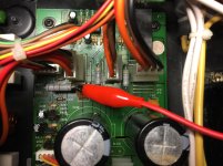
I found the devices on both the schematic and in the amplifier itself. I looked up the spec sheets also for - D1047 and B817 respectively for channel 1. My primary concern at the moment is determining how to see if there is voltage "on" them. This is where my newness shows. Should I measure each of them from Collector to Emitter? Any help similar to "put red probe here and black probe there" would be exceptionally helpful. I understand that these devices can be sensitive, so I'd hate to fry one for the sake of measurement. It seems the builders have tried to make it easy and put pads in a semi-accessible location. Attached is a photo for reference. Apologies for delays in reply. This takes me a bit of time to even begin to understand and come up with thoughtful questions.
With thanks!

We may have reached my intellectual and practical limit. 😀
I found the devices on both the schematic and in the amplifier itself. I looked up the spec sheets also for - D1047 and B817 respectively for channel 1. My primary concern at the moment is determining how to see if there is voltage "on" them. This is where my newness shows. Should I measure each of them from Collector to Emitter? Any help similar to "put red probe here and black probe there" would be exceptionally helpful. I understand that these devices can be sensitive, so I'd hate to fry one for the sake of measurement. It seems the builders have tried to make it easy and put pads in a semi-accessible location. Attached is a photo for reference. Apologies for delays in reply. This takes me a bit of time to even begin to understand and come up with thoughtful questions.
With thanks!
View attachment 797581
He's asking you to confirm the power to the output transistors. You want to measure from the indicated test points to chassis ground. Just find some bare metal on the case and put an alligator clip on it to the negative lead of your multimeter. Almost all measurements should be referenced this way.
The collector of Q119 (left board) and Q219 (right board) should read approximately + 40vdc.
The collector of Q122 (left) and Q222 (right board) should read about -40vdc
That they are nearly the same is more important than the actual voltages.
Be careful with this... From the picture I would touch the jumper going to the collector of the transistor. If you can't do it without the risk of shorting things, don't do it. There are other ways to confirm the power supply.
BTW... what happened here?
Attachments

Last edited:
Keep it simple. Don't get bogged down in power supply issues. The amplifier has 0v on its output and if there is supply to both the +ve and -ve rails, it is probably working.
Confirm there is voltage on U119 and U122 {collectors}.
He's asking you to confirm the power to the output transistors. You want to measure from the indicated test points to chassis ground. Just find some bare metal on the case and put an alligator clip on it to the negative lead of your multimeter. Almost all measurements should be referenced this way.
The collector of Q119 (left board) and Q219 (right board) should read approximately + 40vdc.
The collector of Q122 (left) and Q222 (right board) should read about -40vdc
That they are nearly the same is more important than the actual voltages.
Be careful with this... From the picture I would touch the jumper going to the collector of the transistor. If you can't do it without the risk of shorting things, don't do it. There are other ways to confirm the power supply.
Jon and Douglas - Thank you! I have a bit more understanding of the circuit, but more importantly, I can measure it w/o too much fear of either giving you the wrong readings, unintentionally frying something due to bad measurement technique, or otherwise just screwing it up.
My mains runs at ~120VAC steady.
Channel 1 - Q119: +44V1
Channel 1 - Q122: -44V6
Channel 2 - Q219: +44V7
Channel 2 - Q222: -44V7
So if I am to interpret this properly, the amplifier boards (or at least a portion of them) are seeing the proper rail voltages.
BTW... what happened here?
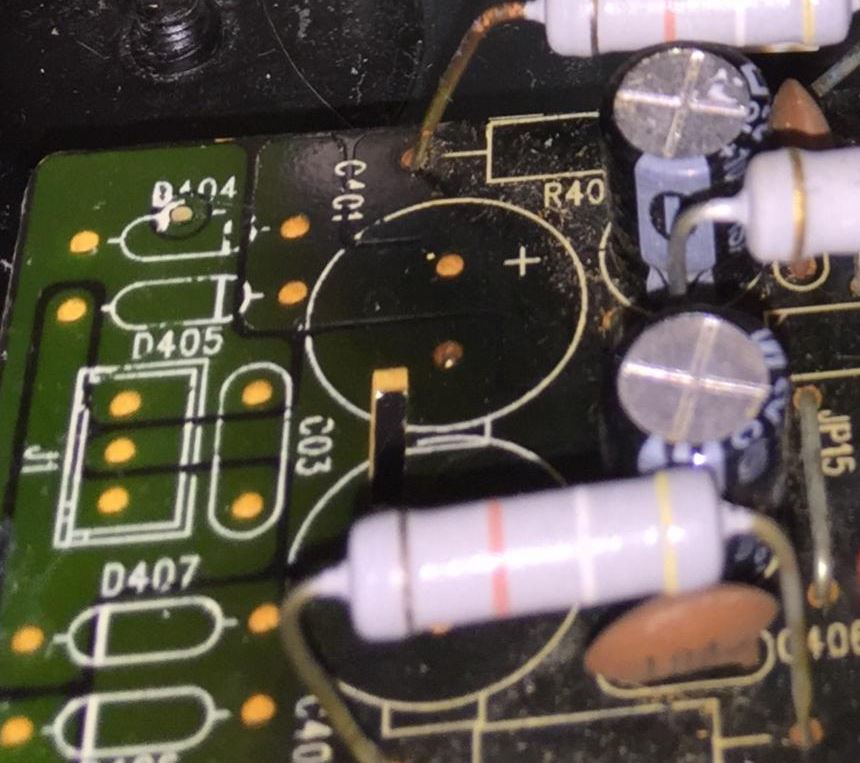
I can't be sure. That section of the board has a bit of discoloration compared to the rest, and one resistor leg has some clear oxidation. My personal best guess is "pet accident" or "spill" from ages ago, but I cannot be sure. When I took that particular board out to replace the relay, I gave it a de-gunking and dedusting with IPA and flux cleaner. I checked continuity with the traces, but I cannot confirm status of any active parts. Thank you for asking. That area gave me pause also. In addition, I think the non-populated parts are for a different amplifier model.
Last edited:
In the interim - I have researched U1 - the Toshiba TA7313P.
It seems I can get them on e-Bay for a reasonable price. From what I've gathered, replacing that little bugger may be the next logical step.
I can't make heads or tails of how to test the part in situ. Is that possible / practical?
Again, I'm thankful for all the help in understanding and clear direction for troubleshooting.
Best,
Patrick
Jon and Douglas - Thank you! I have a bit more understanding of the circuit, but more importantly, I can measure it w/o too much fear of either giving you the wrong readings, unintentionally frying something due to bad measurement technique, or otherwise just screwing it up.
My mains runs at ~120VAC steady.
Channel 1 - Q119: +44V1
Channel 1 - Q122: -44V6
Channel 2 - Q219: +44V7
Channel 2 - Q222: -44V7
So if I am to interpret this properly, the amplifier boards (or at least a portion of them) are seeing the proper rail voltages.
Given that the service manual does not specify the bulk voltages, I'm going out on a limb so say they look alright.
I can't be sure. That section of the board has a bit of discoloration compared to the rest, and one resistor leg has some clear oxidation. My personal best guess is "pet accident" or "spill" from ages ago, but I cannot be sure.
Discoloration like that is a sign of heat.... rather a lot of heat actually. Something pretty bad happened there.
I would take that board out, clean it with rubbing alcohol, let it dry, flip it over and resolder all the connections. Just touch them with your iron to get them liquid and add a tiny bit of resin core solder (I prefer Kester 63/37, lead/tin) to make sure this whole thing isn't just a bad solder joint.
For those corroded resistor leads I would check the points underneath --amplifier unplugged, ohms scale, right across it's legs-- to be sure the resistor wasn't open then brush them down, apply resin paste on the leads and tin them to prevent further corrosion.
When I took that particular board out to replace the relay, I gave it a de-gunking and dedusting with IPA and flux cleaner. I checked continuity with the traces, but I cannot confirm status of any active parts. Thank you for asking. That area gave me pause also. In addition, I think the non-populated parts are for a different amplifier model.
Yep, I checked what I could see against the schematic and I agree those are "not for you, buddy" parts.
- Home
- Amplifiers
- Solid State
- Repair of Alesis RA150