I have a really small CPU fan somewhere - this amp has a 5v output so I might try run it off that to keep the noise down.
Yes and maybe even attach a variable resistor to reduce noise if need be.
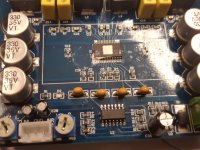
Any experience with this TPA3116D2 board?
I'm making a small sound system for the lady in the kitchen, and figured a cheap class D would do a fine job of driving most speakers at a low cost, will use a bluetooth receiver I already have, since she likes to play music from her phone. Laptop brick for power. Have not decided on the speakers yet, maybe a pair of small Infinities I have in the garage, or maybe build something.
Anyway, I just picked the boards based on looks.. (and low price)
I imagine I see some RC snubbers in the output filters on them? Has been some time since I played around with class D, but remember snubbers in the filter circuit was a good thing to damp out nasty oscillations from the switching.
They is not for 'hifi use' anyway, but if there are some known issues with these boards, I would be thankful for the input.
Attachments

If you plan to power the BT receiver from the same PSU, you may want to consider using BT balanced out -> amp balanced in. Lots of people here fight with ground loops for receiver -> SE inputs when both have the same PSU (i.e. common ground).
The board you've pictured is not one I'd recommend; I've used upwards of 10 TPA3116 boards, of which this one was the worst, in that it is a 'noisy' board (hiss and hum) and the two volume pots are very insensitive. I don't think mine was an isolated case.
In my view, there are better boards out there. My 'goto' TPA3116 is this one:
Assembled TPA3116 class D amplifier board 50W+50W (green pcb) | eBay
In my view, there are better boards out there. My 'goto' TPA3116 is this one:
Assembled TPA3116 class D amplifier board 50W+50W (green pcb) | eBay
Ok, I was hoping to do that, but I do have a separate wall wart for the BT too.
By the way here is the link to the board with more pictures
TPA3116D2 Dual-Channel Stereo High Power Digital Audio Power Amplifier 2*120W | eBay
By the way here is the link to the board with more pictures
TPA3116D2 Dual-Channel Stereo High Power Digital Audio Power Amplifier 2*120W | eBay
The board you've pictured is not one I'd recommend; I've used upwards of 10 TPA3116 boards, of which this one was the worst, in that it is a 'noisy' board (hiss and hum) and the two volume pots are very insensitive. I don't think mine was an isolated case.
In my view, there are better boards out there. My 'goto' TPA3116 is this one:
Assembled TPA3116 class D amplifier board 50W+50W (green pcb) | eBay
Oh, too bad.. ordered already. Hiss and hum is not what I was hoping for! Any simple remedy for it?
I don't care much about the pots, just thought it would be a way to adapt the level to prevent speaker damage (she likes it loud).
Oh, too bad.. ordered already. Hiss and hum is not what I was hoping for! Any simple remedy for it?
I don't care much about the pots, just thought it would be a way to adapt the level to prevent speaker damage (she likes it loud).
Receive it, try it; it may be OK. If you get it and do have some noise, first thing would be to remove the pots completely, but you'll then need some other form of volume control.
Can you remove the TL074? These amps do not need it at all. Most important are the 4x 1uF caps before the inputs of the D-chip, as it decouples DC voltage of the inputs from the source. The 4 in a row near the OP-amp.
If your signal is single ended, 2 caps need to be grounded, the other two are inputs, if you go symmetric you use all 4 open ends of the caps. Maybe change the caps to small film foils.
Rest of the board looks good!
PS twist the heat sink and push carefully at one edge to remove it, usually it is only silcone glue.
Last edited:
Just edited the post. I see now it's just really sensitive on the input signal. Also as mentioned before, the trimmer potentiometers add a lot of noise in the middle position, so they are not really useful for trimming down the sensitivity.
I have to turn down the level from the sound card a lot, and then it's clean, and gives proper output voltage swing.
I have to turn down the level from the sound card a lot, and then it's clean, and gives proper output voltage swing.
As Turbowatch2 says - remove the opamp (or just circumvent it), input through the 1uF coupling caps. Use the balanced inputs of the chip to avoid ground loops if applicable.
It seems fairly ok with the lower input signal. Since I have unbalanced out from the BT-adapter I'm planning to use, I will not get the bridged outputs signal without the opamp, right?
So for now I think I will keep the opamp.
Removed the heat sink, as it was mounted at an angle. Mounted with silicone just as mentioned, and the connection between chip and heat sink was questionable due to poor mounting.
So for now I think I will keep the opamp.
Removed the heat sink, as it was mounted at an angle. Mounted with silicone just as mentioned, and the connection between chip and heat sink was questionable due to poor mounting.
Last edited:
Did a quick distortion measurement with arta (FFT).. The spectrum and distortion levels are not so nice, and they jump up and down a lot with how the input level is varied, but with no real 'logic' to it. At some level, even harmonics dominate, and at other levels odd harmonics dominate etc It just seems the spectrum and levels vary a lot with input level.
Not sure if this has something to do with opamp circuit or not.. but looking at the four beige capacitors, it does not seem they are just normal coupling capacitors with one end to the opamp, and the other to the tpa chip, as far as I can follow the traces. This make me reluctant to unsolder them and try to feed the signal directly. I suspect other things will happen.
Not sure if this has something to do with opamp circuit or not.. but looking at the four beige capacitors, it does not seem they are just normal coupling capacitors with one end to the opamp, and the other to the tpa chip, as far as I can follow the traces. This make me reluctant to unsolder them and try to feed the signal directly. I suspect other things will happen.
Attachments
IMO two caps (on the hot lines) couple to the opamp, the other two on the cold lines are grounded. If your BT receiver has balanced output, feed the four lines directly to the coupling caps. It works OK ( Adding an Amp into Thin-Client PC )
If you remove the caps and feed it directly, you will destroy it. So simple. If you dont want to follow advice, dont ask.
I have described how to handle single ended and symmetric inputs on this chip.
The OP-amp is a typical Chinese stupidity, as it amplifies too much, so you have to reduce the good signal level by a no quality pot and then have a noisy, amplified signal at the D-amp. So all you do ist add noise and distortion of a lowest quality TL074 IC and a much worse pot.
You even measured it. Dont you trust your measurements?
Have a look at the data sheet and do as it is shown there.
Last edited:
OK, now I had a look in the datasheet, and understand it better 🙂
I'm now feeding signal directly to the chip via the caps. Noise is a lot better, and gain is 'normal', seems like gain setting is set to 26dB.
However, distortion still looks bad (to me). The harmonic peaks are moving like waves up in the frequency spectrum when amplitude is varied. The highest diff I could observe between main tone and highest harmonic peak was 60dB, and the worst was 30-40dB.. And there is a lot of harmonics.
Maybe coils etc, but I believe they should add low orders on high current? Or maybe it is as it should be, I see distortion specs are not so good, and harmonic profile is not mentioned anywhere.
Anyway, I think it's 'good to go' for a BT kitchen stereo 🙂
- Home
- Amplifiers
- Class D
- TPA3116D2 Amp