Sören, make yet another mode which makes the DAC conversion rely totally on the clock without any adjustment - please?
//
But how will this work? How will you syncronise incoming clocks to the onboard clock? In the 1941 this is taken care of by the Xmos driver, but what is your idea here? I can only see this working if you bypass the onboard clock and use an external one.
I fear what you are asking for cannot be achieved by firmware alone, or did i get you wrong?
Well I would just see to that whatever drove the s/pdif input was going the same speed as the clock used. An opto splitter? So you are correct - it will be up to external mechanisms to see that the data and clock is synchronous and not the FW in such a mode. Would still need a (really) short buffer to engulf any bit-slips but I assume that the data would stay in memory for a while on the entrance of the DAC as it does today.
//
//
Last edited:
I see two things, possible for I2S input at least, that I would both appreciate to be implemented.
1. An external master clock input mode. The FPGA MCLK OUT at header J3 could be used as input instead. Then the clock of the USB interface could be used or Ian's FIFO.
2. An fixed frequency mode. The FPGA MCLK OUT could be used as master clock of the USB interface. The FPGA should implement some buffer to catch the jitter of the USB interface and the isolator, but not adjust the oscillator frequency in "1Hz" steps as it does now.
2b") With some DIY then one could also replace the SI-clock by some fixed frequency oscillator.
With some DIY then one could also replace the SI-clock by some fixed frequency oscillator.
1. An external master clock input mode. The FPGA MCLK OUT at header J3 could be used as input instead. Then the clock of the USB interface could be used or Ian's FIFO.
2. An fixed frequency mode. The FPGA MCLK OUT could be used as master clock of the USB interface. The FPGA should implement some buffer to catch the jitter of the USB interface and the isolator, but not adjust the oscillator frequency in "1Hz" steps as it does now.
2b
With some DIY then one could also replace the SI-clock by some fixed frequency oscillator.
Last edited:
Nice ideas gents. Now let's see how you can persuade Sören to implement them as it seems like a lot of extra work for no pay. Or will the 1021 sales jump up because of the new features and better sound?
Perhaps one day someone smarter among us will load the FPGA with their own code and make the project open source. It is a lot of work but certainly not impossible. There was even a boot file for the micro floating around at some stage.
Perhaps one day someone smarter among us will load the FPGA with their own code and make the project open source. It is a lot of work but certainly not impossible. There was even a boot file for the micro floating around at some stage.
I totally agree. I've been waiting since 4 years for the Mastermode and it was one of the main reasons to buy the dac. Sending the MCLK to the XMOS through the I2S MCLK OUT and select the Clockfreq with the FSEL IN.1. An external master clock input mode. The FPGA MCLK OUT at header J3 could be used as input instead. Then the clock of the USB interface could be used or Ian's FIFO.
2. An fixed frequency mode. The FPGA MCLK OUT could be used as master clock of the USB interface. The FPGA should implement some buffer to catch the jitter of the USB interface and the isolator, but not adjust the oscillator frequency in "1Hz" steps as it does now.
2b
Implementing everything in one firmware could be difficult, but how about an extra firmware, only with Master and Slavemode?
I do not think there is so much new firmware to develop for that. The 1941 runs already in fixed frequency mode with the USB input. The external master mode additionally would just need to route the clock different.
... of cause it is not me who needs to do it, so I can lightly state such things
... of cause it is not me who needs to do it, so I can lightly state such things
Found a tool for comparing phase noise on the Silabs website. Si570 is substantially better than the Si514 in the audio range, with the delta increasing at lower frequencies.
Oscillator Phase Noise Lookup - Silicon Labs
Oscillator Phase Noise Lookup - Silicon Labs
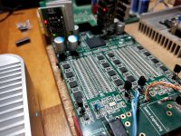
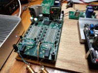
Here's the latest mod on my Soekris DAM v1: the BC550/560 transistor mod
This DAC has come a long way from the unmodded original v1 that sounded just mediocre and 2D,
to now full modded where it sounds sublime and in 3D
It's still my reference now, even against the es9038pro.
This DAC has come a long way from the unmodded original v1 that sounded just mediocre and 2D,
to now full modded where it sounds sublime and in 3D
It's still my reference now, even against the es9038pro.
Attachments
Thanks, I can't tell you anymore.
I think that I replaced the regulators all together if I look in my previous post.
What you can't see in the picture is the backside with plenty of vref caps,
see this old post.
I think that I replaced the regulators all together if I look in my previous post.
What you can't see in the picture is the backside with plenty of vref caps,
see this old post.
is there any improvement in dumping the switching 1.8v regulation?
Very modest compared to other stuff. Not really worth bothering with imo.
I use TORX 147L with my 1021 and 1121 - not one single sync problem during the years.
Squeezbox is the drive.
//
what is the supply voltage you have given to the optical receiver?
I think that the problem when I used the Torx1952 the operating supply voltage is about 4.75V and powering up with 3.3V is making it not to work properly I guess.
Now there are few challenges. There is PWR+5V pin on the dam 1021 board is this digital supply or analog supply which connects to the ladder of the output stage?
Now there are few challenges. There is PWR+5V pin on the dam 1021 board is this digital supply or analog supply which connects to the ladder of the output stage?
I think that the problem when I used the Torx1952 the operating supply voltage is about 4.75V and powering up with 3.3V is making it not to work properly I guess.
Now there are few challenges. There is PWR+5V pin on the dam 1021 board is this digital supply or analog supply which connects to the ladder of the output stage?
I documented my mods a while back
randytsuch's audio page: Soekris R2R Dam Dac - Modding
Ended up changing most of the supplies for batteries. You obviously don't have to use batteries, but if you wade through the information it will help you figure out how voltages are generated and distributed on the card.
Randy
Thank you Randytsuch
There are few things which i want to consider before the optical receiver is plugged to +5V PWR pin.
One as per this image I see that all logic inputs should be 3.3V https://hifiduino.files.wordpress.com/2015/01/r2rconnect.png
So if we are increasing the output voltage to 5V to the optical receiver then its logic output state voltages will be about 4.1 to 4.5V so can that be fed to the SPDIF input 1/2 pins?
- Home
- Vendor's Bazaar
- Reference DAC Module - Discrete R-2R Sign Magnitude 24 bit 384 KHz