Sorry, I meant the scope photos for #29959 didn't get uploaded. Only the schematic.
Again, it works for me.
Why can't Q6 just be a resistor?
Because it is used with various supply voltages and the coil voltage is 24V. Current source keeps the coil voltage. Real input driving circuit was replaced, for simplicity, by a pulse source.
Mark, what do you think is limiting the relay voltage surge? I can see the top is being limited and I don't see any ringing, so resistance seems to be dominating that part of the waveform. If it's the MPSA42, you could find out the collector current and calculate the pulse power. Unfortunately the MPSA42 doesn't get a thetajc graph like the BC337:
https://www.onsemi.com/pub/Collateral/BC337-D.PDF
Here is a 700V TO92:
https://www.onsemi.com/pub/Collateral/FJN3303F-D.pdf
Maybe you can speed up the relay further?
https://www.onsemi.com/pub/Collateral/BC337-D.PDF
Here is a 700V TO92:
https://www.onsemi.com/pub/Collateral/FJN3303F-D.pdf
Maybe you can speed up the relay further?
Last edited:
So nothing like 12% drop.
Of course. Actually, a simple evaluation based on Online Calculator .:. Linear Power Supply Designer tells exactly the same story. I find this online calculator very useful, BTW.
Extract relay coil inductance from turn-off excess delay
Knowing the relay was a TE Connectivity Potter & Brumfield / Schrack RTD34012 with a 12V 33.3mA coil, and knowing that the turn-off delay was 8.7 milliseconds longer with a diode clamp than without, ought to be enough to extract a pretty good lumped circuit approximation of the relay's coil inductance during turnoff. It's an LRD series circuit and we know R, we know D, and we know the ~ 90% fall time. Solve for L.
Don't expect it to match the extracted L from relay turn-on data, since the magnetic circuits in the two situations are quite different: armature pulled-in and touching the coil vs. armature max-distance away.
Relay turn-off was 5x slower with a flyback diode than without.
_
Can anyone explain why? The flyback diode is off till after the coil is off. The only contribution to the circuit is its capacitance which souldnt be very big. Does a smaller diode change the switch time? Is the breadboard adding capacitance? Has anyone simulated the circuit?
Back in the day I was using tv flyback transitors for this kind of application, they were common and could take 1500v. Dont know how available they are now.
Apply the rule of reason. How could a small glass tube dissipate 30 W of energy without becoming glowing hot and starting to emit visible light?* So 12 % of a 2 x 115 W amp, I don't think so.
* there used to be an entire industry founded on that principle 🙂
That is what happens for not starting at the actual post. It is a "100 Watt" rated amplifier that is powered from 120 VAC through a 1 amp slow blow fuse. Not a stereo 120 watt amplifier.
The fuse has a cold resistance of .375 ohms. The current draw is all at the voltage peak when the discharged capacitor is replenished from the AC voltage peak.
Attached is a typical scope shot of the charging current into a filter capacitor.
Note also a fuse can double it's resistance value temporarily and not be damaged.
Attachments
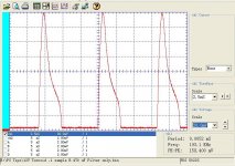
Ed how do we convert displayed millivolts into amps of charging current?
We don't. That chart and everything else that simon7000 blurbs about are obfuscations intended to support the absurdity of "12% lost power due to the fuse" for an 100W audio amplifier.
Everybody and their mothers know about the conduction angle of the diodes charging the filter capacitors, problem is, this has little to nothing to do with the original statement of 12% power loss due to the fuse.
Can anyone explain why? The flyback diode is off till after the coil is off. The only contribution to the circuit is its capacitance which souldnt be very big. Does a smaller diode change the switch time? Is the breadboard adding capacitance? Has anyone simulated the circuit?
When the transistor turns off, the coil will produce however high a voltage is necessary to keep it's current the same. Thus, the relay current will switch to flowing through the diode and then ramp down.
The attraction of the armature to the relay coil depends on coil current. With the freewheel diode, the coil current stays high for longer, resulting in some residual attraction to the armature. Without the diode, the current is forced to zero instantly.
Or perhaps it could be due to the magnetization of the armature inducing a voltage in the coil. When current flows through the freewheel diode, the magnetic field that results opposes the movement of the armature. So remove the diode and you no longer have an eddy braking effect on the armature.
Last edited:
Same deal Ed, get rid of it.... It is a "100 Watt" rated amplifier that is powered from 120 VAC through a 1 amp slow blow fuse...
That is what happens for not starting at the actual post. It is a "100 Watt" rated amplifier that is powered from 120 VAC through a 1 amp slow blow fuse. Not a stereo 120 watt amplifier.
The fuse has a cold resistance of .375 ohms. The current draw is all at the voltage peak when the discharged capacitor is replenished from the AC voltage peak.
Attached is a typical scope shot of the charging current into a filter capacitor.
Note also a fuse can double it's resistance value temporarily and not be damaged.
So what. Drawing 10 amps drops the 170 pk voltage to 166 volts.
As almost always, a non-issue will be dissolved in bits and pieces. Just for the reason to keep the line and not to lose one's face.
- Status
- Not open for further replies.
- Home
- Member Areas
- The Lounge
- John Curl's Blowtorch preamplifier part III