
Hello Valerie,
Very nice results! It does remind me of my own adventure in this, very similar, in 1997, see attached. I called it 'On Demand Feedback' 😉
Even got a patent on it. 😎
Jan
Hi Jan,
Thank you! 🙂
Very interesting paper indeed.
I like the low loop gain approaches. I'm still not quite sure about the reasons - although I have some ideas - but they sound really good 😎
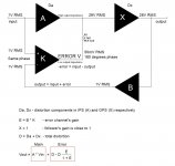
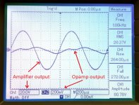
Attached are ODNF approach explanation, used in Simpelstark, and practically measured error channel output screenshot.
Cheers,
Valery
Attachments
Second channel up! Everything went up smoothly with the modifications for 39V.
Here's a screenshot of the second amp after being adjusted. It will now be playing on the suicide speakers for a while but so far, seems to sound wonderful! 🙂
All the best!
Do

Here's a screenshot of the second amp after being adjusted. It will now be playing on the suicide speakers for a while but so far, seems to sound wonderful! 🙂
All the best!
Do
BTW, what power can I be expecting from feeding the amplifier 39V and a 4 ohms load (more like ~3.5 ohms)?
Hi Jan,
Thank you! 🙂
Very interesting paper indeed.
I like the low loop gain approaches. I'm still not quite sure about the reasons - although I have some ideas - but they sound really good 😎
Attached are ODNF approach explanation, used in Simpelstark, and practically measured error channel output screenshot.
Cheers,
Valery
Yes that is clear to understand. What you always run into with this and similar subtractive concepts is the need to accurately subtract or add signals very precisely to obtain a distortion minimum. I didn't follow this thread in detail but I guess that was also something you had to solve.
If you have read Giovanni Stochino's error correction and error feedforward articles in Linear Audio you know that!
Jan
Exactly - amplitude and phase (!) precision are very important for the best result.
Cheers,
Valery
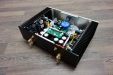
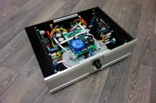
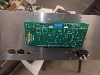
Second channel up! Everything went up smoothly with the modifications for 39V.
Here's a screenshot of the second amp after being adjusted. It will now be playing on the suicide speakers for a while but so far, seems to sound wonderful! 🙂
All the best!
Do
View attachment 788504
Beautiful!
Cool piece of aluminum across the input pairs - it's good to have them thermally coupled to minimize the offset drift.
Careful build = no smoke 😛
Do,
Salut, you have built it well.......
It really is a very clever topology and impresses me. Please let us know about the sound quality, we really know just about everything else!
Hugh
Salut, you have built it well.......
It really is a very clever topology and impresses me. Please let us know about the sound quality, we really know just about everything else!
Hugh
BTW, what power can I be expecting from feeding the amplifier 39V and a 4 ohms load (more like ~3.5 ohms)?
If your PSU is powerful enough - no rail sagging at high swing - you will have up to around 120W per channel before clipping.
22V RMS at the load with still a bit of headroom.
Beautiful!
Cool piece of aluminum across the input pairs - it's good to have them thermally coupled to minimize the offset drift.
Careful build = no smoke 😛
Yeah, nice chunk of alu, hehe. It is there just temporary until I bond the JFets together. Can't wait to hear this amplifier on my main speakers!
Do,
Salut, you have built it well.......
It really is a very clever topology and impresses me. Please let us know about the sound quality, we really know just about everything else!
Hugh
Hi Hugh, thanks for the comment! I will definitely let you know how it sounds. Just waiting on my speaker protection modules before connecting them to my ATS-4 speakers.
If your PSU is powerful enough - no rail sagging at high swing - you will have up to around 120W per channel before clipping.
22V RMS at the load with still a bit of headroom.
Cool! I have two Cresnet SMPS600. Should be plenty enough power per module. If not, I'll just grad a custom 600VA transfo with quad secondary to feed two independant PSUs and up the voltage to 48Vdc (I'll probably will have to change R15-R18 again).
Jeff, Valerie,
I have a question about the amp control board V6... If I'm assembling a dual mono setup (two PSUs, two amp modules, etc...) in a single chassis and adding the amp control board, will the amp control board connect the gnd of the two amp modules together, or will it keep the grounds totally isolated on each amp module?
My aim is to keep everything separated, especially gnd.
Thanks
Do
Jeff, Valerie,
I have a question about the amp control board V6... If I'm assembling a dual mono setup (two PSUs, two amp modules, etc...) in a single chassis and adding the amp control board, will the amp control board connect the gnd of the two amp modules together, or will it keep the grounds totally isolated on each amp module?
My aim is to keep everything separated, especially gnd.
Thanks
Do
Hi Do,
The amp control board V6 will keep the grounds isolated from each other.
It utilizes the optocouplers for keeping its own digital ground and two amplifier channels' grounds separated.
That's exactly the way my own Simpelstark prototype is built - two PSUs, two amp modules, amp control board V6 in the middle - all grounds are separate.
Very low noise, no ground loops, very low cross-talk - as if those channels would be two separate monoblocks.
Cheers,
Valery
Attachments
Everything is isolated in the amp control systems. Each audio ground is completely isolated, as is digital ground. Digital power is completely self contained. Any connection to the audio electronics is completely separated through either opto-isolators or relays.
Having just completed a Hawk A-18 (no audio GNFB) and got great results, I am now interested in this project. I have registered with vzaudio.com and sent a couple of messages to request access to the build guide... but no luck so far.
Can anyone help me, please?
Can anyone help me, please?
Hi Dave.
We're having issues with our website messages getting sent to spam in our Gmail account so some of these requests are getting missed. We'll get your access going.
We're having issues with our website messages getting sent to spam in our Gmail account so some of these requests are getting missed. We'll get your access going.
Having just completed a Hawk A-18 (no audio GNFB) and got great results, I am now interested in this project. I have registered with vzaudio.com and sent a couple of messages to request access to the build guide... but no luck so far.
Can anyone help me, please?
Hi Dave,
My fault - gmail keeps sending some messages to SPAM folder

You can download the docs now - sorry for delay 😉
Cheers,
Valery
ok, thanks for the answers.
I'll be using two SMPS with this build but would like the speaker protection module along with the control board V6. I don't think I need the temperature sensors... Not running full power ever and not class A and the heatsink is pretty beefy... Anyways, I could always use them.
What would you suggest I get from you?
Do
In this case, you need the main board and 2 x DC detect boards. Although a bundle including 2 x temperature sensor boards will be very good I think.
Cheers,
Valery
Cheers,
Valery
The Amp Control 6V2 system will work fine with the SMPS, you can just leave the soft-start relay and resistor off the board and change the code to bypass the softstart (easy change).
If you haven't got the rear cover of the chassis drilled yet I'm going to have a new system together in a couple weeks that stacks the control board on the speaker relay board right on the rear panel and will have a smaller power supply board designed for SMPS. This is the system I was telling you about with the optional front panel display and touch switch power button.
If you haven't got the rear cover of the chassis drilled yet I'm going to have a new system together in a couple weeks that stacks the control board on the speaker relay board right on the rear panel and will have a smaller power supply board designed for SMPS. This is the system I was telling you about with the optional front panel display and touch switch power button.
Attachments
- Home
- Amplifiers
- Solid State
- No-global-loop amplification