I would again check for a possible short between input RCA outer GND and chassis.
Checked, infinite resistance.
Please try rotating the transformer.
Is the hum there all the time or only when you connect a common ground source?
That’s a bit difficult, leads are stiff and short.
Maybe because you have a system wide ground. Single.Grrr, it’s a cross channel ground loop!
How about making two virtual grounds: a left one and a right one?
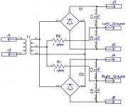
How about adding two (or 4) resistors, 1 ohm each, between the return of the left ground and center tap, and the return of the right ground and center tap?
Can you please provide a drawing of the fragment of the schematic, where you have the secondary windings, all the rectifier bridges, the filter caps, ... and at which spot do you specifically do you "fork out" to the left and to the right?
IMO, the right channel does not really care about the left channels ground, and vice versa. Maybe you could build on that.
Last edited:
>>>There are four bridges in total, each channel has two separate diode bridges for positive and negative rail built with MUR860.
... but only two transformer windings, is that correct? So you fork out left/right from transformer windings to a set of two left bridges and a set of two right bridges, yes?
How about getting rid of two bridges, and reducing the bridge count from 4 to 2 ?
So that you have One Bridge, spanning from positive to negative rail, for each of the channels?
Then, you could come back to the "Center-Tap" architecture, and make the following:
The right-ground return to the transformer center tap via a 1 ohm resistor, and
the left-ground return to the transformer center tap via a 1 ohm resistor.
The right amplifier (as well as the left amplifier) will not really care about these resistors, because most of the current will be flowing between the Rails and the local (left/right) ground anyway. So these resistors are not necessarily "in the high-currents" paths. (If I am full of bull here, please correct me.)
The preceding statement regarding the 1 ohm resistors assumes that you have separate filtering banks for the left channel and the right channel. The assumption being that: Most of the action will be happening between the Right_Amplifier and the Right_Filter_Bank and (independently) between the Left_Amplifier and the Left_Filter_Bank.
Divide et Impera !
Divide and rule - Wikipedia
Last edited:
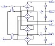
This is a slightly different layout of the same 4 bridge concept as in previous post.
Maybe more clear as to the intended workings.
Question: Will it work, or is there a flaw in here somewhere?
If one ohm resistors will prove insufficient to kill the inter-channel ground loop, then maybe increasing them to 2.2 ohms would help?
Maybe more clear as to the intended workings.
Question: Will it work, or is there a flaw in here somewhere?
If one ohm resistors will prove insufficient to kill the inter-channel ground loop, then maybe increasing them to 2.2 ohms would help?
Attachments
... withdrawn.
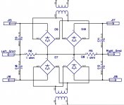
Error in schematic.
The more I think about it, the more I am convinced that it is not possible to do it with four bridges fed by two windings.
But the two-bridge version should work.
Error in schematic.
The more I think about it, the more I am convinced that it is not possible to do it with four bridges fed by two windings.
But the two-bridge version should work.
Last edited:
Via the preamp?
Yes. Not sure how the loop is closed via 4 bridges though on the other end. First end is through input/output coaxial cables. When I disconnect input cable on either channel, humming stops.
I connected two grounds with thick cable (thicker loop🙂 and humming went down significantly, but it's still there. I need to find a way to break it completely.
To repeat: You "will" have cross channel hum if you power two channels with one set of secondaries. It doesnt matter how many bridges you stick in, or how many HBRs you use. I struggled with this exact same config for weeks. There are other threads here about this.
That's good, what's your source is the preamp necessary?
Preamp is passive LDR with input switcher. Even without preamp, grounds will connect through a source grounds.
That doesn't matter it won't create a loop. The most important thing is to keep the area within any loop smallEven without preamp, grounds will connect through a source grounds.
How about something like this?To repeat: You "will" have cross channel hum if you power two channels with one set of secondaries. It doesnt matter how many bridges you stick in, or how many HBRs you use. I struggled with this exact same config for weeks. There are other threads here about this.
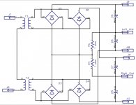
One set of secondaries. Four Bridges.
Two ground separating resistors, for left ground and right ground.
The charge currents flowing through the resistors essentially compensate themselves to null, I believe, so they do not increase the impedance of the PSU, as seen be the amplifier boards.
But then, these resistors also serve the double purpose of HBR resistors, separating the left/right ground.
Will this work?
Is there a flaw in here somewhere, like diodes shorting the secondaries, and I do not see it?
...
And what about the circuit as posted in post #66 ?
Attachments
Last edited:
Hum is quite faint now, I can hear more the transformer humming than hum from the speakers. This now might be something different, maybe inductive coupling.
Which of the many proposed changes / actions did you implement, so as to achieve this bettered result?Hum is quite faint now, I can hear more the transformer humming than hum from the speakers. This now might be something different, maybe inductive coupling.
Which of the many proposed changes / actions did you implement, so as to achieve this bettered result?
I connected into star two channel star grounds and preamp ground.
You've reduced the loop area. Keeping the RCA terminals close and gnds connected at the sockets helps. Where is the star?
Last edited:
- Home
- Amplifiers
- Solid State
- Transformer HUM.