Are You sure it's not the chassis humming vibrating or even vibration coupling through the furniture ? Try to put some rubber feet underneath the chassis. You said You have two lives. In Belgium I believe You have a live phase and a neutral wire or three live phases and a neutral and of course the PE earth wire should be there also. I lived in Germany so standards are the same. If you connect two live wires (black or / and brown) You are feeding the trany with 400V and not 230V. Neutral wire is usually blue. The one that doesn't light the screwdriver neon lamp.
I'm pretty sure I am feeding transformer with 230V, otherwise I would not be writing this. There is 3X230V and no neutral, like in many old houses in Belgium.
My gut feeling is that the transformer(s) are of lesser quality than they should be. Hence, would you be inclined to try:
1). a Zobel on the AC secondaries of the transformer, just prior to the rect bridge?
Just two elements in series (WAG): 100nF + 75ohms/2W.
This idea is intended to kill any ill effects of the stray inductance of the transformer, resulting in rectifier spikes on the diodes when switching from forward to reverse blocking.
2). small capacitors to mellow down, partially alleviate the rectifier spikes on the bridge, connected in parallel to each of the diodes within the bridge. An extremist audiophile would actually add some damping to them, such that it would actually be the small capacitor in series with a small resistor.
Example: 75 ohms + 47nF rated at least 2.2 times the respective DC rail voltage.
Irrespective of the former, you you have any small valued series resistors within the rail filter module just after the rectifiers? As a means to measure dropout and hence estimate the current flowing through the rail? My curiosity is going in the direction of verifying if the positive rail current is comparable/equal to the negative rail current. Are they of similar values.
Does the hum subside if the transformer and rectifier and filtering are running under "no load" conditions (the amplifiers disconnected from PSU) ?
Does the hum persist if you power a well heat-sinked resistive dummy load, one with a current draw comparable to the amplifier boards themselves? (I am talking about the mechanical hum of the transformer itself here).
Are we 100% sure that the rail voltages are as they should be and that no diode in rectifier bridge is faulty?
Is it a single rectifier bridge feeding both the positive and negative rails, with center taps and midpoint of capacitors as ground rail, or are you using two separate rectifier bridges for positive rail and for negative rail?
Is it at all possible, a scenario, such that a single blown diode (failing into 'open circuit', as opposed to a 'short') could be causing that one of the rails is partially driven by a half bridge (60Hz) and not a full bridge (120Hz) rectification?
Last edited:
My gut feeling is that the transformer(s) are of lesser quality than they should be. Hence, would you be inclined to try:
1). a Zobel on the AC secondaries of the transformer, just prior to the rect bridge?
Just two elements in series (WAG): 100nF + 75ohms/2W.
This idea is intended to kill any ill effects of the stray inductance of the transformer, resulting in rectifier spikes on the diodes when switching from forward to reverse blocking.
2). small capacitors to mellow down, partially alleviate the rectifier spikes on the bridge, connected in parallel to each of the diodes within the bridge. An extremist audiophile would actually add some damping to them, such that it would actually be the small capacitor in series with a small resistor.
Example: 75 ohms + 47nF rated at least 2.2 times the respective DC rail voltage.
Irrespective of the former, you you have any small valued series resistors within the rail filter module just after the rectifiers? As a means to measure dropout and hence estimate the current flowing through the rail? My curiosity is going in the direction of verifying if the positive rail current is comparable/equal to the negative rail current. Are they of similar values.
Does the hum subside if the transformer and rectifier and filtering are running under "no load" conditions (the amplifiers disconnected from PSU) ?
Does the hum persist if you power a well heat-sinked resistive dummy load, one with a current draw comparable to the amplifier boards themselves? (I am talking about the mechanical hum of the transformer itself here).
Are we 100% sure that the rail voltages are as they should be and that no diode in rectifier bridge is faulty?
Is it a single rectifier bridge feeding both the positive and negative rails, with center taps and midpoint of capacitors as ground rail, or are you using two separate rectifier bridges for positive rail and for negative rail?
Is it at all possible, a scenario, such that a single blown diode (failing into 'open circuit', as opposed to a 'short') could be causing that one of the rails is partially driven by a half bridge (60Hz) and not a full bridge (120Hz) rectification?
There are four bridges in total, each channel has two separate diode bridges for positive and negative rail built with MUR860. Hum is equally present on both channels, very unlikely that multiple brand new diodes failed at the same time on both of them. There are no resistors after rectifiers. Mechanical hum coming from transformer itself is barely noticable, as opposed to the hum in the speakers.
I will check the rest later, thanks for suggestions so far.
Extremist Mode Enable.
So, why not try the following:
Dismantle the transformer out of the amplifier chassis.
Dismantle the Power Supply Modules, with main rectification, filter cap et al, out of the amplifier chassis.
Prepare 2 x 3 leads, 2 meter length, leads for the +,0,- for each of the channels (left/right) respectively. If I understand correctly, 6 leads is all you need to achieve total geographical separation of the Transformer+PSU from "All_Rest_Of_Amplifier".
Assemble the amplifier in such a fashion, that the transformer, Bridge and PSU is 2 meters away from the amplifier.
Make a tight braid of three leads for the (+,0,-) strands going to the left channel.
Make a tight braid of three leads for the (+,0,-) strands going to the right channel.
Take the two above and make a tight twisted pair out of them, so that there is as small as possible gap between them, hence minimizing the loop area.
Two meters geographic separation between mains transformer and the amplifier proper is enough to eliminate any "magnetic coupling" from the transformer / PSU to the amplifier.
At the receiving side of this 2x3 twisted braids line, provide for some additional, local rail decoupling caps, if not already ample on the amplifier boards.
If the hum in the speakers still persists, then it is most probably not a problem originating from the transformer, not a magnetic coupling at least.
... irrespective of the above ....
Maybe it would be worth trying to make four simple Ripple Eaters for each of the supply lines, just to be sure that the hum is not disseminated via supply rails? What kind of RMS current (magnitude) do you have on those supply lines?
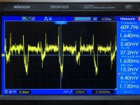
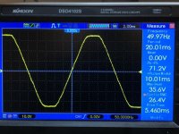
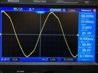
Do you have a scope, and the capability of looking at the quality / stability of the voltage, as being forwarded from the PSU to the amplifier boards? What does the rail voltage actually "look like"?
Last edited:
+1I presume/hope you've tried shorting the inputs.
The activity/suggestion may seem very basic,
but could have been forgotten about - in all the emotions and frenzy.
Ok, this following idea may seem really ... stupid.
How about taking an interstage, 1:1 galvanic insulation transformer, just for the sake of conducting a test.
This may not necessarily be the best choice of device, but for test purposes, would probably suffice:
PULSE TRANSFORMER 1.1 MINIATURE | eBay
with winding ratio in the whereabouts of 1:1, you could provide signal to the inputs of the amplifier, but at the same time providing for total galvanic separation of the amplifier and whatever Rest_Of_System that you have on the source side.
Because it may well be that you are trying to fix an amplifier, that is not at all broken. If the amplifier is perfectly operational, it will be difficult to fix it.
So why not go back to the beginning and test if the amplifier is faulty or in perfect operating order?
Since you have two amps that are identical, why not run the secondary wires from one unit to the other to rule out the transformer issue?
I presume/hope you've tried shorting the inputs.
Preamp shorts the inputs few seconds during power up, still a hum as soon as transformer is on.
I did a test with another 225VA 2x24 transformer, outside the chassis, around 50cm away. It was less hum, but still there. Should I increase the distance?
I also replaced one front end power supply (LM317 based) with another, which is LT3062 based. Hum stayed the same.
I also replaced one front end power supply (LM317 based) with another, which is LT3062 based. Hum stayed the same.
Are you certain everything is isolated from the chassis? The fact that connecting 0V to the chassis massively increased the hum is telling.
Are you certain everything is isolated from the chassis? The fact that connecting 0V to the chassis massively increased the hum is telling.
Yes, measures infinite resistance from ground to chassis (earth). When I connect them, hum increases a lot.
Since you have two amps that are identical, why not run the secondary wires from one unit to the other to rule out the transformer issue?
That's exactly what I did earlier today. I opened working amp which is actually two monoblocks in same chassis and rerouted one of the transformers to the problematic amp. And there was a hum again! Connected transformer back to working amp to verify under same conditions and there was no hum. I guess that rules out the transformer.
So next step will be to connect DC rails after filter caps from working amp to non-working amp. The only difference in backend PSU PCB between the two, is the voltage rating in filter caps - silent amp has 63V caps, humming one has 50V caps, same capacity and brand.
Please try rotating the transformer.
Is the hum there all the time or only when you connect a common ground source?
Is the hum there all the time or only when you connect a common ground source?
- Home
- Amplifiers
- Solid State
- Transformer HUM.


