USSA 5.1
That would be great that you build an USSA5.1 since you could compare it to your USSA5 🙂
The only problem is to get you USSA5 pcbs....
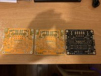
This is my only option right now from my remaining stock..
One black pcb : not an option
2 yellow pcbs but 1oz copper without gold immersion, lower quality in general
I would need a miminum of 5 pairs of pcbs to start a new small group buy...
Fab
Hi meanieNice work Vunce!
USSA5 is still my current favourite, now looking for time to complete my SLB ps for it.
I also don't mind building another using Darlingtons output instead of Mosfets.
That would be great that you build an USSA5.1 since you could compare it to your USSA5 🙂
The only problem is to get you USSA5 pcbs....
This is my only option right now from my remaining stock..
One black pcb : not an option
2 yellow pcbs but 1oz copper without gold immersion, lower quality in general
I would need a miminum of 5 pairs of pcbs to start a new small group buy...
Fab
Attachments
Last edited:
I have a toroidal transformer rated 0-18@7A dual rails and with my CRC psu comes to around +/-27vdc. And I hope I can use this transformer for this amp.
thanks
thanks
Hi manniraj
If you have 36vac total at 7A that gives 252VA. Normally I would recommend 200VA or more by channel. However it may be fine also with less power depending on the speakers used and the power demand need....🙄
I am surprised you get +/-27vdc rectified with only 2x 18vac...😕
I suppose it may be possible with a no loss active bridge, very small R and with no load connected🙄
With 27vdc you would get more class AB power but you may have to reduce class A power (lower bias current) for the same heatsink size.
Fab
Last edited:
I would need a miminum of 5 pairs of pcbs to start a new small group buy...
Fab
Hi Fab,
If you opened a small GB I don’t think you would have a problem getting a few takers. I have plenty of Sanken Darlingtons from the preamp...... 😀
Group buy USSA5 pcb ??
It is true that the difficulty of the USSA3 and 5 was to obtain the rare obsolete expensive and matched mosfet drivers ....🙄
With no match requirements of current production of relatively cheap (but excellent !) bjt as drivers that makes the amp easy to obtain all parts.🙂
I will let the people manifest here for a small group buy interest...
Fab
"Is it true that the difficulty of the USSA3 and 5 was to obtain the rare obsolete expensive and matched mosfet drivers ...."
I would image that this would stop a large number of people building this amp.
Fab I sent you an email via diyaudio.
I would image that this would stop a large number of people building this amp.
Fab I sent you an email via diyaudio.
Harry3
I have not received your email.
Peoples having difficulty sourcing the mosfet drivers for their USSA5 pcb could probably replace the mosfet by the selected bjt and perform the required resistors changes accordingly...
Fab
I have not received your email.
Peoples having difficulty sourcing the mosfet drivers for their USSA5 pcb could probably replace the mosfet by the selected bjt and perform the required resistors changes accordingly...
Fab
Last edited:
Hi manniraj
If you have 36vac total at 7A that gives 252VA. Normally I would recommend 200VA or more by channel. However it may be fine also with less power depending on the speakers used and the power demand need....🙄
I am surprised you get +/-27vdc rectified with only 2x 18vac...😕
I suppose it may be possible with a no loss active bridge, very small R and with no load connected🙄
With 27vdc you would get more class AB power but you may have to reduce class A power (lower bias current) for the same heatsink size.
Fab
I get this +/-27vdc on my CRC psu with my home mains voltage goes upto 240v rather than 230v sometimes. Hence this output dc voltage is with no load. I am using 0.47R 3W Panasonic resistors 4 per rail with 22000uf *4 caps per rail. Yes I think my transformer is rated under VA compared to the required as per your recommendation. But I think it should work fine with 252VA for both the channels.
Thanks
Let me start up the GB for USSA5.1 aka BJT/Darlingtons.
Fab, once it hit your min order quantity, you may order them in any colour of your choice, preferably not in Black, so as to differentiate between the MOSFETs and Darlington pcbs.
meanie - 2 pcs
Fab, once it hit your min order quantity, you may order them in any colour of your choice, preferably not in Black, so as to differentiate between the MOSFETs and Darlington pcbs.
meanie - 2 pcs
preferably not in Black, so as to differentiate between the MOSFETs and Darlington pcbs.
Good suggestion Meanie.
Fab,
How about purple PCBs? 🙂
Good start manniraj
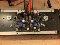
For C2 you should use something better than the Wima. Use at the minimum the other indicated part number from Panasonic: ECW-FE2W475J. Even better to use ECW-FD2W475J. The latter part is quite good for the price. As you can see there is enough room on the pcb to put a lot bigger cap.
Fab
Hi Fab, a quick question regarding my above pic where I soldered going through the manual. I have soldered those black color R15,16 resistors (0.05 OHMS 1% 3W) as well on to the PCB and I hope they are fine for the initial setup and recording the voltages etc.,
Thanks
Hi manniraj
Until you solder M3/M4 these resistors are not part of the circuit so it will be fine.
Fab
Until you solder M3/M4 these resistors are not part of the circuit so it will be fine.
Fab
Last edited:
I get this +/-27vdc on my CRC psu with my home mains voltage goes upto 240v rather than 230v sometimes. Hence this output dc voltage is with no load. I am using 0.47R 3W Panasonic resistors 4 per rail with 22000uf *4 caps per rail. Yes I think my transformer is rated under VA compared to the required as per your recommendation. But I think it should work fine with 252VA for both the channels.
Thanks
Ok then you will see or....rather hear 😉
Fab
Small group buy for pcb of USSA5/5.1
Thanks meanie🙂
I just want to clarify that until now the pcb layout should stay the same for both USSA5 and USSA5.1 schematics. Only driver and Input/driver current changes so far. Therefore there should be no need to differentiate them. If there is any change to pcb layout then the pcb layout version would pass from version 0.4 to 0.5. Also Have in mind that there are already red, blue , black and yellow colour pcbs sent to builders.
And for zman01 purple colour suggestion it does not exist at my pcb manufacturer supplier...🙄
However, I will select the most popular colour for the new buyers so please indicate your choice.
I just started to assemble one channel of USSA 5.1 with my single remaining black pcb to test it electrically to verify performance against original USSA 5 so stay tuned...
Fab
Let me start up the GB for USSA5.1 aka BJT/Darlingtons.
Fab, once it hit your min order quantity, you may order them in any colour of your choice, preferably not in Black, so as to differentiate between the MOSFETs and Darlington pcbs.
meanie - 2 pcs
Thanks meanie🙂
I just want to clarify that until now the pcb layout should stay the same for both USSA5 and USSA5.1 schematics. Only driver and Input/driver current changes so far. Therefore there should be no need to differentiate them. If there is any change to pcb layout then the pcb layout version would pass from version 0.4 to 0.5. Also Have in mind that there are already red, blue , black and yellow colour pcbs sent to builders.
And for zman01 purple colour suggestion it does not exist at my pcb manufacturer supplier...🙄
However, I will select the most popular colour for the new buyers so please indicate your choice.
I just started to assemble one channel of USSA 5.1 with my single remaining black pcb to test it electrically to verify performance against original USSA 5 so stay tuned...
Fab
Attachments


Last edited:

- Home
- Amplifiers
- Solid State
- USSA-5 Build with Review