Good stuff. I noticed in the footnotes had nothing older than 1989
Mills P.G.L., Hawksford M.O.J. (1989), Distortion Reduction in Moving-Coil Loudspeaker Systems Using Current-Drive Technology, J. Audio Eng. Soc., 37, 3, 129–148
and ...
https://pdfs.semanticscholar.org/2e6b/5b6ec83e229c1ab06108f731582de7368298.pdf
and
https://www.klippel.de/fileadmin/_m...ON_OF_NONLINEAR_LOUDSPEAKER_DISTORTION_02.pdf
..... electrodynamic loudspeakers can be used as sensor itself while reproducing a signal at the same time. The back electromotive force (EMF) produces a direct relationship between the electric input signals at the loudspeaker’s terminals and the velocity of the voice-coil. A detector system as shown in Fig. 9 requires only the measurement of the current and voltage by using a simple shunt or a inexpensive current sensor. The velocity is estimated by an nonlinear algorithm derived from the voltage equation on the electric side or from the force equation on the mechanical side of the loudspeaker model. That results in highest accuracy possible while introducing a minimal number of unknown parameters which have to be identified. The detector is made adaptive to make the identification of the unknown parameters feasible while reproducing an audio signal. Adaptive detector algorithm have been developed which behaves stable and robust
anyway,
All amps ought to incorporate the principle I showed in TAA 1985. Just one resistor and lower driver distortion. More accurate sound.
Good mod project for the DIY'er.
THx-RNMarsh
Seems a passing interest to most. Was there any drawback or perhaps the advantage was not considered significant enough for your own current use?... It was very long time ago... 1980's. ... reduce THD from speaker...
I use very similar setup learned from Rod Elliot's site on my LM1875 with 0.22 R sense resistor.
Last edited:
Good input Richard! That's the stuff we need.
Of course, you will now be subjected to Murphy's 2'nd law: 'It exists, but it is not important.' Wait till they 'rediscover' it and put it in their own name in future. '-)
Of course, you will now be subjected to Murphy's 2'nd law: 'It exists, but it is not important.' Wait till they 'rediscover' it and put it in their own name in future. '-)
Seems a passing interest to most. Was there any drawback or perhaps the advantage was not considered significant enough for your own current use?
I use very similar setup learned from Rod Elliot's site on my LM1875 with 0.22 R sense resistor.
LOts of people use it since 1985. Those who care for a more accurate sound. Just as they have changed to lower DA caps and better amp topologies and dc servo and cleaned up their ac power lines. But when you publish in an small obscure publication (TAA), it takes longer to reach critical mass (the established large mfr).
BTW - Joe Rasmussen. has published it also using same for his amp.
Yep..."Wait till they 'rediscover' it and put it in their own name in future. '-)" already happened.
THx-RNMarsh
Last edited:
The real issue with loudspeakers is they are a complex mix of acoustics, mechanical engineering, and electrical engineering.
From my expertise, I can see where these experts fall short in their understandings. But I can only critique them when it is within my domain.
Loudspeaker(s)+listening room+listener(s), you're missing two important factors
just make clear of what I said. It works if you are a vendor 😎How much does one have to know to be an expert?
So how about measuring 3kHz and up and on-axis with the tweeter ?. The impedance graph does not show expected impedance rise, this is why I have asked twice for loudspeaker schematic please.
You have not asked a better question yet, what is the impedance of the tweeter. Plot attached. Please read the values from the graph. Further low rise of impedance at high frequencies is due to series resistor in the crossover.
Dan, measuring "3kHz and up" again shows no difference in acoustical distortion, with and without parallel R across amplifier output. Please have a look at driver schematics
John Curl's Blowtorch preamplifier part III
and try to realize that this "parallel R across amplifier output that would be consuming EMF" is a nonsense. EMF is applied across R2+L2 (voice coil resistance and inductance) and these driver components make the whole damping. Or voice coil together with crossover.
Please note that you need 5 seconds to ask me for new measurements and I need half a day to prepare, perform and evaluate the measurement. You just ask random questions and if one is answered, you immediately come with another one, again illogical question. For this reason, my recommendation for you is to learn and make such measurements by yourself.
Attachments

Good input Richard! That's the stuff we need.
Of course, you will now be subjected to Murphy's 2'nd law: 'It exists, but it is not important.' Wait till they 'rediscover' it and put it in their own name in future. '-)
"It exists, but it's not impedance"
😱
🙄
nor reactance...of air, maybe...
Ah ah ah you haven't read Joe's important page about acoustic phase inversion in a tweeter. A must if you want to go inside the matter ( pretty obscure, quite black...magic)Dan, measuring "3kHz and up" again shows no difference in acoustical distortion, with and without parallel R across amplifier output. Please have a look at driver schematics
😛
nope. not Lots before. Probably, as here, because they dont/ didnt understand how and why it works.Before too 😉
Now then.... terminating the long speaker cable at the speaker with a moderate R in parallel.........
BTw, these things are audible under typical use in the home. Low series R and Ls was the basis of the original Monster Cable.
Much later, I had Demian Martin listen to parallel R and he heard more accurate sound also and we included it in one of the more developed high-end cables for Monster.
But these changes/mods dont come out of no where. And, of course, like the Rs/amp mod for lower speaker THD, if it isnt understood or explained correctly, it is dismissed. Only those who have long cables and listen will buy it.
-RM
Last edited:
Nope, probably they did/do understand how and why it works, that's why it has been used for a long time.nope. not Lots before. Probably, as here, because they dont/ didnt understand how and why it works.
Various forms of "mixed mode feedback" have been around, not only for speakers but as well for line-output transformers, spring reverb drivers, etc. For those, the established output impedance is usally negative but that doesn't negate the principle ;-)LOts of people use it since 1985. Those who care for a more accurate sound.
[...]
BTW - Joe Rasmussen. has published it also using same for his amp.
Yep..."Wait till they 'rediscover' it and put it in their own name in future. '-)" already happened.
Adding a GND leg current sense to a standard feedback network is a very easy and stable way to increase amp output impedance to some tens of ohms but in the end it is just a random shot again, though with a better gun.
To exploit the full performance increase a scheme is needed where a VC current signal is mixed with an (extracted) VC velocity signal, frequency dependant preferably. The terminal voltage is a 1st order approximation of velocity signal sensor, polluted with the ohmic drop R*i (neclecting the inductance here). Some of this R*i drop can be cancelled (negative Z_drive) but the more you do so the less stable is the residual impedance (thermally, mostly). Then enter analog bridge design with dynamic R_dc changes servoed out and using better models of the static VC impedance etc, and from there all the way to the Klippel approach of adaptive nonlinear modelling to effectively pre-distort the power-amp input signal, using digitized voltage and current and lots of fast DSP. Finally, speaker mfgrs will adopt to this trend (besides making better drivers in general) with designs that are not strictly optimized for standard voltage drive... to this date, there are only few drivers of this kind...
Yes, and since there have been articles doing just that. Most get far more complicated than a single resistor.
Here is a buffered version from 2006 DIYAudio....

Lots to choose from if you look. I am a little surprised the electronic brains here couldnt describe the operation which causes THD to be lowered though. Such an old concept. I am not sure those implementing the concept really understand why, either.
THx-RNMarsh
Here is a buffered version from 2006 DIYAudio....
Lots to choose from if you look. I am a little surprised the electronic brains here couldnt describe the operation which causes THD to be lowered though. Such an old concept. I am not sure those implementing the concept really understand why, either.
THx-RNMarsh
Last edited:
Yes you'd think JC, the self-proclaimed speaker expert in this thread, would know. 😕I am a little surprised the electronic brains here couldnt describe the operation which causes THD to be lowered though.
Such an old concept.
More stories about dead horse, aka impedance flattening
As there was no change of acoustical distortion measured after “impedance flattening” at power amplifier output, I made some measurements of voltage distortion at the amplifier output, where we may expect changes after addition of the parallel resistor, because load impedance is decreased.
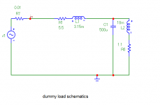
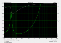
For the experiment a RLC dummy load was chosen, schematics is attached. L2 inductor has a ferrite core, so it becomes highly nonlinear at higher voltages. Measured impedance plot of the RLC load is attached as well. We can see that at 40Hz, the load impedance magnitude is 17 ohm, however phase angle is +45°. So 40Hz was chosen as one measuring frequency. The second measuring frequency is 1kHz, to fulfill Dan's request to measure at inductive portion of the impedance.
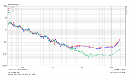
Measurements were done for voltage range 30mV – 20V, which means up to 100W/4ohm power. At 40Hz, we can see that the distortion is lowest for the nonlinear RLC load (green plot) up to 10V. Then, the ferrite L2 non-linearity starts to play the game and distortion between 10V and 20V is increased. Distortion for RLC with parallel 4ohm flattening is highest up to some 15V. The reason of very small difference between 15-20V is questionable.
At 1kHz, distortion with RLC is the lowest one and for RLC//4ohm is the highest one.
As there was no change of acoustical distortion measured after “impedance flattening” at power amplifier output, I made some measurements of voltage distortion at the amplifier output, where we may expect changes after addition of the parallel resistor, because load impedance is decreased.
For the experiment a RLC dummy load was chosen, schematics is attached. L2 inductor has a ferrite core, so it becomes highly nonlinear at higher voltages. Measured impedance plot of the RLC load is attached as well. We can see that at 40Hz, the load impedance magnitude is 17 ohm, however phase angle is +45°. So 40Hz was chosen as one measuring frequency. The second measuring frequency is 1kHz, to fulfill Dan's request to measure at inductive portion of the impedance.
Measurements were done for voltage range 30mV – 20V, which means up to 100W/4ohm power. At 40Hz, we can see that the distortion is lowest for the nonlinear RLC load (green plot) up to 10V. Then, the ferrite L2 non-linearity starts to play the game and distortion between 10V and 20V is increased. Distortion for RLC with parallel 4ohm flattening is highest up to some 15V. The reason of very small difference between 15-20V is questionable.
At 1kHz, distortion with RLC is the lowest one and for RLC//4ohm is the highest one.
Attachments

C'mon, the mechanism is well understood by many here.I am a little surprised the electronic brains here couldnt describe the operation which causes THD to be lowered though.
Drive impedance change results in :
- different mag and phase SPL response (to be eq'd out for comparisions)
- different local velocity feedback in the driver itself, around resonance
- different impact from the unstable Le behaviour, Le(x) mostly
- ... some change in lesser factors ...
In many cases, going from zero ohms Z_source to some 10s of ohms can give some net distortion benefit for typical use cases but it's not a given and it won't reach optimum as well ("optimum" behaviour may be a very floating target, though).
All this parallel R stuff is a nonsense anyway - the best way to drive speakers is one amp per driver, amp located close to the driver. Then the only cables (though preferably use optical connections) are line level. Also all the issues of crossover networks (high power simple passive filters) are gone.
Back to current drive, and it's ability to reduce driver distortion. In a 3 way tri-amped speaker, which drivers would benefit from current drive?
Back to current drive, and it's ability to reduce driver distortion. In a 3 way tri-amped speaker, which drivers would benefit from current drive?
He said he knows more about speakers than anyone else in this threadJC doesnt claim to be a speaker Expert.
I asked for loudspeaker schematic because of the low rise in impedance at HF as shown in original graphs, so yes I did ask in a round about way. I see crossover series resistor is reducing magnitude of resonance peak and spreading the impedance peak as would be expected.You have not asked a better question yet, what is the impedance of the tweeter. Plot attached. Please read the values from the graph. Further low rise of impedance at high frequencies is due to series resistor in the crossover.
Like I said In the case of 'zero' impedance cable and 'perfect' amp there should be essentially no difference with parallel resistor, I do not disagree with you there. However this is not the same as typical 'mid-fi' amp or receiver with lousy cable and this is where the application of 'local' damping becomes useful, and this is where Joe's crossover/speasker is aimed.....ie the typical family budget limited 'enthusiast' with dual useage AV receiver. This is where your sweeping generalisations do not apply because most listeners do not have access to the optimised system that you have.Dan, measuring "3kHz and up" again shows no difference in acoustical distortion, with and without parallel R across amplifier output. Please have a look at driver schematics John Curl's Blowtorch preamplifier part III and try to realize that this "parallel R across amplifier output that would be consuming EMF" is a nonsense. EMF is applied across R2+L2 (voice coil resistance and inductance) and these driver components make the whole damping. Or voice coil together with crossover.
I do thank you for your efforts and realise that such measurements are not trivially easy or fast. However your system is not typical and data applicable to say a Pioneer/Yamaha etc budget amp or AV receiver would be much appreciated and useful...and educational for all.Please note that you need 5 seconds to ask me for new measurements and I need half a day to prepare, perform and evaluate the measurement. You just ask random questions and if one is answered, you immediately come with another one, again illogical question. For this reason, my recommendation for you is to learn and make such measurements by yourself.
Dan.
- Status
- Not open for further replies.
- Home
- Member Areas
- The Lounge
- John Curl's Blowtorch preamplifier part III