Wrong richard question.Ed was insulted the last time he contributed measurements (on resistors, as I remember), but he would be the best person to ask.
Richard, I have not followed your topic here with this added resistor, but it seems to me that many cables are also helped by termination with a Zobel network R+C, or just an R (if it can handle enough power and approximates the cable characteristic impedance. It would seem to me that too low a value of R, would not match the cable, but would also load the amp significantly. What are we talking about here?
He posted a schematic partial showing a .15 ohm resistor inserted into the speaker return leg, the fb divider connected to that instead of ground. A partial current feedback scheme that seemed to have reduced some thd.
jn
No speaker "experts" needed in this thread. Speaker trivialities are discussed, however basic knowledge is necessary to be able to discuss even these trivialities.
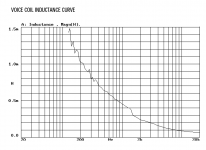
This might be interesting. The plot shows how voice coil inductance of the small woofer depends on frequency.
This might be interesting. The plot shows how voice coil inductance of the small woofer depends on frequency.
Attachments
This might be interesting. The plot shows how voice coil inductance of the small woofer depends on frequency.
Several things conspire to do that.
1. shorted turns. Either a shorting ring in the structure, or a full aluminum vc former.
2. Eddy exclusion of the vc flux lines from the conductive pole tip and front plate.
jn
John,
At any rate, I've better things to do than to have an old coot who lives in the 70's insult me and everyone else. Believe it or not, many things have changed since 1975, and for the better.
-Chris
I see you are nowhere near done insulting everyone around here. Because, considering your comments, even I am a speaker expert compared to you. Many are way more knowledgeable than I am on the topic. But, I used to design speaker systems and get paid for doing so as a regular part of my job. Later I was responsible for designing and implementing campus paging systems (70 V line type). I am sure there are many people that can run rings around me, but apparently I am running rings around you!.I am not a loudspeaker expert, but I know when people actually do know more about them than me, and that does not include any of you guys.
At any rate, I've better things to do than to have an old coot who lives in the 70's insult me and everyone else. Believe it or not, many things have changed since 1975, and for the better.
-Chris
Personally I'd welcome all honest expert proficient in his field. But I agree that nobody spreading loaded words, half truths with intention less than honorable is acceptable, including any "expert".No speaker "experts" needed in this thread...
Believe it or not, many things have changed since 1975, and for the better.
-Chris
Lots of rehashing goes on here of tinkering and tweaking from the 70's and 80's which is simply irrelevant nostalgia by now. Some cling to it more than others.
I personally am trying to cling to my youth from the 70's.
Alas, no joy..
Jn
It's that kind of ground loop action I was thinking of w/r to Richards mixed feedback circuit. I am thinking he altered the ground return path and as a consequence, the coupling of speaker currents to the input circuitry.
Jn
Alas, no joy..
Jn
Thanks for the link, I missed that thread.
It's that kind of ground loop action I was thinking of w/r to Richards mixed feedback circuit. I am thinking he altered the ground return path and as a consequence, the coupling of speaker currents to the input circuitry.
Jn
Hi Scott,
The 70's were a fantastic time to be alive. I certainly miss some people I knew well then. But overall, today is great, technically speaking. Music ... not so much.
Today we have wonderful test equipment and fantastic parts compared to those dark days in the 70's. We all made the most of it and enjoyed the sun a lot more. Even cars had more character (I wish the fuel economy and power of today was available then!).
Today we have it so good, but I really miss being a teenager and in my early 20's. We got away with so much it wasn't funny. Not today! But then, we didn't go around killing each other either.
-Chris
Within his area of expertise, he is good.Malcolm Hawksford? I know him well! Thanks for the link. Ask JN about him! '-)
His Essex echo article...not within his wheelhouse.
Abysmally inaccurate.
Jn
Ed was insulted the last time he contributed measurements (on resistors, as I remember)
Really, I thought it was the other way around.
Today we have it so good, but I really miss being a teenager and in my early 20's. We got away with so much it wasn't funny. Not today! But then, we didn't go around killing each other either.
For sure. As I mentioned before at the Media Lab at MIT we bought a piece of equipment that would not fit through the door so we got some sledge hammers and knocked down the wall. Facilities came by the next day and said WTF and fixed it. No one was ever bothered by the incident.
Last edited:
I know not the mechanism, but almost all parts that specify inductance do so @ 1 kHz and also 10 kHz . Sort of ruins any semblance of a pure measure , as in Ohms, or Farads ......... Obviously cannot plot a L.R. response curve without first having a L.F. curve of the D.U.T........Several things conspire to do that. 1. shorted turns. Either a shorting ring in the structure, or a full aluminum vc former. 2. Eddy exclusion of the vc flux lines from the conductive pole tip and front plate. jn
For all the coils, inductors, and magnets I make or purchase, I have the tests done from 20 hz to 10 or 20Khz for the first articles. That picks up shorted turns, shorted laminations, or any hardware that happens to form a shorting loop around any laminations.
So I see a lot of inductor roll off. Some at 100 hz, some 2khz, my air core litz made 50 kHz. 360 pieces in two sizes. Had the vendors do 5 frequencies as a QA screen, we never received a bad unit.
Jn
So I see a lot of inductor roll off. Some at 100 hz, some 2khz, my air core litz made 50 kHz. 360 pieces in two sizes. Had the vendors do 5 frequencies as a QA screen, we never received a bad unit.
Jn
Last edited:
Yes, I liked the 70's! I did plenty too. I also designed speakers, including my part with the Grateful Dead 'Wall of Sound' where I made the acoustical measurements of frequency response and distortion on the speakers that we ultimately used, then I worked side by side with John Meyer in Switzerland where we made a really nice 3 way, time aligned, powerful, 3 amplifier driven all horn loaded speaker system. We were one of the first people to use fft analysis for loudspeaker design in 1974. 1 year later, I was paid to design a 3 way, 2 amplifier driven, direct radiator woofer, mid range horn with a 3 tweeter spread array. Of course, I had to design the electronics for all these speakers as well, if I could not buy something that worked well enough. For the Meyer JM/C we used two powerful Marantz amps, a 500 and a 250, but I had to make the amp for the tweeter, back in 1974. It became the JC-3, and is now available (in some form) out of China through AliExpress. It also evolved into the Levinson ML-2 a few years later. It is similar to the JC-3, but with more current drive capability.
Today, I work as a consultant for 4 companies, designing old fashioned discrete analog products. We still use complementary j-fets, because they are the best that we have found available at any price. I am not 1/2 the man that I was in the '70's, but I still do OK.
Today, I work as a consultant for 4 companies, designing old fashioned discrete analog products. We still use complementary j-fets, because they are the best that we have found available at any price. I am not 1/2 the man that I was in the '70's, but I still do OK.
So how about measuring 3kHz and up and on-axis with the tweeter ?. The impedance graph does not show expected impedance rise, this is why I have asked twice for loudspeaker schematic please.I have shown 40 - 300Hz, however I measured 20Hz - 20kHz. Though the plots are not nice above woofer cone critical frequency and due to crossover frequency and phase interactions between woofer and tweeter, distortion is same for the speaker with and without "impedance flattening" in the whole range 20Hz - 20kHz.

Ok, but we are back to 'ideal' and 'perfect' conditions.....who has real world zero impedance cables and real world zero output resistance/infinite DF amplifier ?. Pavel I think it would be useful to repeat your test and measurement with an 'ok' quality stereo amplifier or better still a typical AV receiver. I have stated that I have 75R across each end of my speaker cables and that one resistor failed O/C was audible because of shift in channel balance and noise/graininess on the offending channel. Perhaps the perceived improvements of 'impedance flattening are due to attenuation of RF pickup and consequent audible secondary effects ?. Pavel, your work is good but not telling the whole story for real world. Dan.This procedure of impedance flattening is the dead horse in case that a standard solid state amplifier with voltage output and very low output impedance is used and of course capable to drive the complex load.
Yes, that test has actually been done. It was very long time ago... 1980's. Using SoundTech analog distortion analyzer. Which led to My investigating this and the adding of the Rs in series with the speaker and its voltage drop summed with amp neg input.Do you have test results that correlate to that? THD at each end of an 18 zip?
I honestly think that Ed would be more interested it this effect as he runs rather long speaker cables, a thousand feet more or less.. I wonder if he has any plots..
jn
Since I published it, many many people tried it with their own amps. So, I am fairly sure it isnt a grounding issue.
But, go ahead and explain how exactly it would reduce THD from speaker.
See AES convention paper 8844. "Distortion Improvement In the Current Coil of Loudspeakers" 2013 may 4-7
"Thus, the electromechanical conversion linearity is decreased by the impedance variation, which implies a reduction of the overall audio quality. A current driving method could reduce the effect of the non-linear impedance by controlling the coil current directly, thereby the acceleration. Large signal impedance modeling is given in this paper to underline the non-linear effects of electrodynamic loudspeaker parameters on the coupling. As a result, the practical comparison of voltage and current driven methods proves that the current control reduces the voice coil current distortions in the three different loudspeakers under test."
THx-RNMarsh
Last edited:
I would like to talk about electronics modifications again.
I would like that, too. Do you have some particular mods in mind? (note I am interested in electronics mods, not magic beans)
I would like that, too. Do you have some particular mods in mind? (note I am interested in electronics mods, not magic beans)
🙂🙂🙂🙂🙂
Try doing this --->
View attachment Marsh MFB ckt.pdf
-RNM
Last edited:
THD reductionSince I published it, many many people tried it with their own amps. So, I am fairly sure it isnt a grounding issue.
But, go ahead and explain how exactly it would reduce THD from speaker.
THx-RNMarsh
View attachment MFB_2.pdf
-RNM
Comparative Measurements on Loudspeaker Distortion: Current vs. Voltage Control
Esa MERILÄINEN Current-Drive - The Natural Way of Loudspeaker Operation
Modulation and harmonic distortion produced by ordinary moving-coil direct-radiator drive units are measured under current control and voltage control. A realistic two-tone test signal is used to investigate the detrimental effect of the voice coil electromotive forces on the voltage-to-current conversion that is critical with voltage control. Dramatic improvements in distortion performance are obtained with current control. Current nonlinearities in voltage-controlled speakers are shown to be the dominant source of modulation and odd harmonic distortions at signal frequencies above the fundamental resonance region. Currents in conductive voice coil formers also seem to be significant sources of distortion; with current control and non-conductive formers, odd harmonics and related modulation products virtually vanished in the upper midrange.
Full Text: PDF
- Status
- Not open for further replies.
- Home
- Member Areas
- The Lounge
- John Curl's Blowtorch preamplifier part III