measured both : 5.1V .
the gate drivers are efficiently supplied from the 5007 dcdc buck converter.
that one has a reference voltage of 1.25V contrary to the other brands, such that the 14K (15C) and the 1.6k (162) resistor divider returns a 12V from the dcdc.
the gate drivers are efficiently supplied from the 5007 dcdc buck converter.
that one has a reference voltage of 1.25V contrary to the other brands, such that the 14K (15C) and the 1.6k (162) resistor divider returns a 12V from the dcdc.
measured both : 5.1V .
the gate drivers are efficiently supplied from the 5007 dcdc buck converter.
that one has a reference voltage of 1.25V contrary to the other brands, such that the 14K (15C) and the 1.6k (162) resistor divider returns a 12V from the dcdc.
Ohh, no, I mean those 3 in parallel near buck converter! They died here, dunno with what to replace them! 🙁
well, these are in series with the buck converter Vin, so most likely your XL5007 is dead.
the XL5007 can handle 80V, no idea why these 3 zeners in paralell are there connected in series with the input, only to reduce the max input voltage to allow a smaller size inductor. beware that the standard on-semi LM5007 has a 2.5V reference, so you may have to adjust the resistor divider when using a US based part..
are you sure the xl5007 is still working ?
The irs2092 is a strange beast.
It took me a good while to work out how to do it without getting resets oon high power.
Also on power down I was getting massive thumps through the speaker !
I had to incorporate a shutdown circuit that monitored VCC and held the 2092 in reset if VCC got too low.
It took me a good while to work out how to do it without getting resets oon high power.
Also on power down I was getting massive thumps through the speaker !
I had to incorporate a shutdown circuit that monitored VCC and held the 2092 in reset if VCC got too low.
this board has an NTC circuitwith Q3, Q4, and an output sensing Q6, Q5 circuit to connect to the CSD pin5 to shut it down.

I soldered one out to measure it and it was 16V
Thank you!!!
Yes, I am sure XL7005 is dead 😀 SWitching pin is shorted to ground, already replaced it, also IRS2092 is dead, replaced that too! Amp works now, the only missing part was zener value! I soldered one 24V 5W zener, will see how long is this gonna last! 😀 Thank you so much for info!!! Greatly appreciated!
well the lower the voltage on Vin , the higher the current will be through XL5007 input and the zener. given the efficiency of the XL5007 a higher voltage is always better, until we hit the saturation of the 221 (220uH) inductor. on the other hand the efiiency of the XL5007 drops at higher input voltages. the 0504 inductor can handle 0.35A. the datasheet indicates the use of a 47uH inductor all the way till 80V input.. now that I'm reading the datasheet, this one is completely different from an LM5007, as it has a bipolar switch, and does not need a boost cap. the base drive is regeulated down from Vin, so that may affect the efficiency indeed. so a blocking of the fan may result in a too high load on the converter . a 24V zener 5W may be the good solution, to keep the XL5007 in a happy Vin range.
Finally got myself three of these boards to play with the other day. The data sheet for the IRS2092 says max voltage is 200V, that is, +/- 100V. The recommended voltage on various ebay listings is +/- 65V. What is the cause of the limit here? Have they cut too many corners in the board layout? Dodgy second rate parts? Does it work okay but reliability goes down the toilet?
Also I noticed it won't work on rails less than about +/- 45V. Is there some voltage divider resistor for undervoltage sensing that I could change so I could run it on a lower voltage that might be available in an existing amplifier .
Also I noticed it won't work on rails less than about +/- 45V. Is there some voltage divider resistor for undervoltage sensing that I could change so I could run it on a lower voltage that might be available in an existing amplifier .
Oftentimes the output MOSFETs' voltage ratings determine the max voltage. If they use a 200V rated FET then the maximum quoted (in IRAUDAMP7S info) is +/-70V. I'd guess a FET rated over 250V would be needed to reach the maximum of the IRS2092.
Yes there is often an undervoltage lock-out which disables the amp when the rails are too low. You can indeed change the zener (normally its a zener rather than a resistor divider) but this might not be the only change you need to get it to work well. For example they often implement simple zener (shunt) regs for the analog rails (+/-5V) and with lower power rails those might get current-starved. In that case you need to reduce a few resistor values.
Yes there is often an undervoltage lock-out which disables the amp when the rails are too low. You can indeed change the zener (normally its a zener rather than a resistor divider) but this might not be the only change you need to get it to work well. For example they often implement simple zener (shunt) regs for the analog rails (+/-5V) and with lower power rails those might get current-starved. In that case you need to reduce a few resistor values.
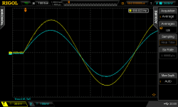
Okay, here it is running on +/- 65V. Load is 12 paralleled 100 ohms = 8.333 ohms. I could actually go slightly higher output than the scope screen shot here. Max 60V peak = 216 watts. Trace averaged over 128 passes to get rid of switching noise and show the basic waveform. Gain is x300 which is a bit much IMHO. Was mentioned somewhere earlier. On +/- 65V the output inductor gets to about 65 deg above ambient with no signal.
Attachments
Actually, yes. My very first post here was a thread I started just over 17 years ago describing my adventures with one.Do you know what "a circlotron stage" means in electronics, son? The old way of making a "full bridge" as it is called in modern switching electronics.
On +/- 65V the output inductor gets to about 65 deg above ambient with no signal.
Likely either the core or the windings (or both) are too lossy. Do check that the oscillation frequency isn't too low - the IR paper suggests it should be 400kHz in the idle state. Too low a frequency will increase the quiescent inductor current, boosting losses.
Frequency is 175kHz. Too low?Likely either the core or the windings (or both) are too lossy. Do check that the oscillation frequency isn't too low - the IR paper suggests it should be 400kHz in the idle state. Too low a frequency will increase the quiescent inductor current, boosting losses.
What is the cause of the limit here? Have they cut too many corners in the board layout? Dodgy second rate parts? Does it work okay but reliability goes down the toilet?
Probably a bit of all of that. Mine also had filter caps rated for 100 V but some boards are rated less (80 V). I fully expect the first thing to fail on these will be some cap.
Mine has 100V caps. And right next to the hot toroid too. That wont help cap life.Probably a bit of all of that. Mine also had filter caps rated for 100 V but some boards are rated less (80 V). I fully expect the first thing to fail on these will be some cap.
Frequency is 175kHz. Too low?
For sure, inductor current will be more than double that at 400kHz. Does your board have a preset pot you can adjust?
Next thing to sus out is the gain. Way too high. I think that would make it susceptible to picking up its own noise. Gain issue mentioned here -> Ebay amp - is 500W believable?
Yep. Just a bit scared of blowing it up, that's all. Why wouldn't they set it to a higher frequency ex factory? Mosfets run hotter?For sure, inductor current will be more than double that at 400kHz. Does your board have a preset pot you can adjust?
Possibly they don't measure and adjust the idle freq at all in production. Yes FETs will run warmer at higher freq, as will the IRS2092. However 175kHz might be low enough to impact the audio quality - it gets even lower at high output levels as its a self-oscillating (rather than clocked) design.
- Home
- Amplifiers
- Class D
- eBay amp - is 500W believable?