Here is a schematic for the board along with a couple of mods. The gain issue due to R13 has been documented above. I also found the negative current limit kicked in way too soon, positive being fine, and so suggest a change to R11, see attached pdf.
The inductor and heatsink are not up to job of continuous full power output but when testing with music via a limiter that just went to clipping, the temperature of the heatsink was low enough that I could touch it for quite a few seconds and the inductor was cooler. I don't see that as a problem. No problem getting clean 380W into 4 ohms.
I used 8AT HRC fuses in the power supply lines and 5AT in the speaker as an average maximum power of limit 100W to the speaker seemed reasonable for music to me.
Thanks for the schematic!
I have this module. It works very correctly, but the out filter coil is very hot. Even with minimal load. It should be like this?
Thanks
Thanks
Hello,
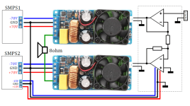
I connected two modules to the bridge. When one module is running alone (not BTL), the drop of Vc to 56V does not matter. But in BTL shutdown at 63V. I have 4 pairs (4 BTL). Connection completely identical. Only one works without downtime. And it also heats up less. The other 3 falling out and warm up IRS2092.
Where can the error be?

You might want to check a few things:
1. The non-inverting op-amp should have 10K-100K input resistor to ground- missing in your sketch
2, Check the IRS2092 Module for the updated resistor Values. R13 from 100 to 3.01K Ohm and R11 from 10K to 8.2K Ohm
3. Set RV1 for 400 kHz (both modules set to same frequency or offset > 25 kHz from each other
4. Ensure power supply droop is not excessive
I believe the resistors are 1206 outline from the E96 series. And please let us know what you find. Thanks- EVMan
Here is a schematic for the board along with a couple of mods. The gain issue due to R13 has been documented above. I also found the negative current limit kicked in way too soon, positive being fine, and so suggest a change to R11, see attached pdf.
The inductor and heatsink are not up to job of continuous full power output but when testing with music via a limiter that just went to clipping, the temperature of the heatsink was low enough that I could touch it for quite a few seconds and the inductor was cooler. I don't see that as a problem. No problem getting clean 380W into 4 ohms.
I used 8AT HRC fuses in the power supply lines and 5AT in the speaker as an average maximum power of limit 100W to the speaker seemed reasonable for music to me.
D7 and D8 are positioned before the inductor in the scheme but there are no diodes in parallel with drain and source on the board.
The mosfets are 31N20 with trr of 200ns and require the body diodes to be replaced (they must be before the inductor and in parallel with the drain and source). I suggest adding something like the mur120 with a trr of 35ns to the board, or replacing the original mosfets.
- Home
- Amplifiers
- Class D
- eBay amp - is 500W believable?