You know what, I am done with offering you, "Tournesol" anymore of my input. Sorry Krisfr, I was generally trying to help you out because i understand where you are coming from, this guy I have no more time for. Krisfr, if you start your own thread I'll help you but I am done with Tournesol. I would advise you to consider why you are helping this guy out, use me as your example.
Last edited:
It seems KiCAD is becoming a favourite of a lot of component manufacturers and distributors. Digikey has created a lovely set of 7 videos on YouTube just explaining KiCAD. It's a kind of very simple tutorial series which takes you through the complete cycle of making a flashing-light toy using KiCAD, right up to ordering the PCB after designing it. I found that video series very useful. I had tried KiCAD before, and my earlier knowledge of Eagle was causing problems. KiCAD's written tutorial was not helping me much. But this video series just made everything fall into place beautifully. I later found plenty of other help and guidance videos from other sources on KiCAD on YouTube.Is there a KiCAd thread?, I will look in the tools section. If there is not then users should start one up like the ltspice one..
So,if you ask me, forget about a thread on these forums -- just install the latest KiCAD first, then go study the 7-part Digikey video series. You'll be 95% there.
YouTube
Very nice and friendly attitude.You know what, I am done with offering you, "Tournesol" anymore of my input. Sorry Krisfr, I was generally trying to help you out because i understand where you are coming from, this guy I have no more time for. Krisfr, if you start your own thread I'll help you but I am done with Tournesol. I would advise you to consider why you are helping this guy out, use me as your example.
This said, your only inputs where the obvious gate stoppers (that are on the final schematic) and the Cordel protection against an event that can never happen with the protection I indicated as intimate part of the project because, with pro and cons that can be discussed, it will not allow any major clipping. Among the pros, a speed to fire that the protection you indicated will never approach. The speed of the relay+ some µs, whatever happens: short circuit, DC in the output, oscillation I.E. any difference between input and output signal, instantly.
Do you enter in a Mercedes garage and talk to their clients of the advantages of BMWs ?
That is exactly what you did here. And my answer was probably nicer than the one that could had been the one of the garage manager.

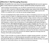
In yellow, a 1µs parasitic signal, in red the speaker output voltage.
Last edited:
I think we should not forget that nobody 'owns' a thread here. Anyone can discuss anything in a thread as long as it is reasonably on topic.
It is bad form to attack a person because his ideas and proposals do not fit your agenda. You can use offered ideas or not, that is your call, but it is against the spirit of this forum to try to silence someone because you don't like his ideas.
I am very concerned that this thread kills the spirit of this forum, and mods seem just to let it happen.
Jan
Jan I don't know against who of us two this is addressed, but it seems that I was A LOT less aggressive than this "guy".It is bad form to attack a person because his ideas and proposals do not fit your agenda. You can use offered ideas or not, that is your call, but it is against the spirit of this forum to try to silence someone because you don't like his ideas.
I am very concerned that this thread kills the spirit of this forum, and mods seem just to let it happen.
How would you react if you proposed to the community (it is free, isn't-it ?) a solid state amplifier and someone would come on the topic to propose an another amp ... tube based?
With the insulting side that goes with it ?
That's the spirit of this forum? If so, I give-it up.
And, please, notice that is not "My amp", i can do-it all by myself, that i usually do, but an attempt to explore some original ideas in a collaborative spirit. And, about collaboration, only two members were really involved.
Last edited:
And, about collaboration, only two members were really involved.
Lots of others gave ideas and proposals, but you worked them all out because you didn't like the ideas. This is NOT your thread, you didn't 'give' anything for free, all ideas here are for free as soon as you type them in.
You don't seem to understand the concept of an open forum. Maybe you should re-read the rules you read when you joined.
Jan
You know, i'm very sad.That's why I've kept my mouth shut, Monsieur Le Professeur")
Get a lot of critics, few encouragements. When somebody make a suggestion (usually without data to support-it) I consider, as i do with my own ideas, the pro and cons. And argue to try to get more convincing elements if the suggestion was not so convincing after try. (the Cordell protection diode assembly that brings 6dB more distortion)
But the same people that argue against one or another aspect of this project do not accept any argue against their own suggestions ?
My goal was to explore what can happens if we try to design a CFA with the same methods than a VFA. High open loop gain, lot of feedback, and their consequences (reduced slew rate, descending open-loop response from low frequencies, no free lunch).
It is (was?) an exploration to figure out if the character of a CFA (if any) is due to the speed, low feedback, flat open loop gain in most of the audible range, or just its "current" on demand.
i have not the slightest Idea of how it will sound. As it is the exact opposite of what i design usually. For sure I have demonstrated that it is possible to design a CFA with VERY low distortion that is the usual crtitic of the CFA opponents.
Too, the use of an optional error correction is an attempt to figure out how low we can hear them...
And I had critics on each and every points of this approach. And now the protection ?
It is hopeless.
Sorry to tell this, Jan, but I had explored or evaluated all the suggestions done. Including the few of yours in topic, most of them known from decades. Sorry to not had found yours always giving real improvements, or in the line of this project. And again, in your usual manner, YOUR post is aggressive, attacking the person, including your ugly call to the moderators, while I never said something that was against the rules.Lots of others gave ideas and proposals, but you worked them all out because you didn't like the ideas. This is NOT your thread, you didn't 'give' anything for free, all ideas here are for free as soon as you type them in.
You don't seem to understand the concept of an open forum. Maybe you should re-read the rules you read when you joined.
Jan
No argue with you any more. May-be no more post from me at all, if it is just to share and exchange with nice, benevolent and friendly people like you that seems to be here only for commercial reasons.
Life is too short.
And, yes, I have done something for free: a lot of work, hours of simulations and print screens.. What about you ? Just words to show how good you are.
Insults, now, without anything to justify them,. (This guy, syn08, was in my ignore list since the early begining). With no comments on his own ridiculous work. (Just a little search is enough)
The pack won. I unsubscribe and leave this place too badly attended.
Sorry, and many thanks, Krisfr and spladski and others helpful and nice people. I leave in the middle of the way, but you can understand: too much is too much.
The pack won. I unsubscribe and leave this place too badly attended.
Sorry, and many thanks, Krisfr and spladski and others helpful and nice people. I leave in the middle of the way, but you can understand: too much is too much.
Last edited:
I am the person who laid out the diyAudio Store product called "M2X" PCB, using KiCad (here is a link). The portion of that board which interfaces with the "Universal Mounting Specification" pattern of holes on the diyAudio Store heatsinks (link2), took me about 30 minutes. You will find that laying out boards which meet the UMS spec, is straightforward and uncomplicated.
Last edited:
 come on guys, it is not enjoyable to delete posts, stick to the topic on hand...
I have a question as to the correctness and best practice of putting one or two 220uf or 1000uf capacitors right on top of the output transistors as close as possible to the lead of the transistor to have as much current available to the transistor at all times. Which is better, one 220uf or 2 1000uf? Thanks
No one answered this question before. Please, I would like to know the answer if someone would share their knowledge with me. Thanks
No one answered this question before. Please, I would like to know the answer if someone would share their knowledge with me. Thanks
Do you mean 2 x 220 OR 1000? You also said 220 OR 2 x 1000.
Basically of course the higher is better but there is a point of diminishing return. Anything over a single 1000 should not make much difference.
And don't take 'on top of it' too literally. What you want is keep circulating current local and not going up and down all the way to the supply.
What could be a good idea is to place a good film cap as close as possible, like 1uF or so. That can enhance stability.
Jan
I scanned a sub-section from the previous edition (5th) of Douglas Self's book "Audio Power Amplifier Design". The latest and greatest edition of the book is the sixth, which is copyright 2013. The 5th edition, which is the one quoted below, came out in 2009.
_
_
Attachments
Last edited:
Totally agreed. I think it is a good idea to decouple with low capacitance low ESR caps of polymer type. Some 47uF maybe enough for the job of high-frequency decoupling. This comes in 10x20mm cases and 5mm pitch for instance. The bulk caps of several 1000uFs are to be placed close to the rectifier and transformer.
Krisfr, because i don't like to let things unfinished, find attached the schematic of the simple protection.
Credit to Esperado.
An ultimate amp protection circuit ?
www.esperado.fr - Protection d'amplificateur ultime
The static relays are in two options. One unique with a low serial resistance one (IP80225N10N3), or 3 (IRF3710ZG) in parallel, each of higher impedance, to reduce any distortion they could produce or losses of damping factor.
In an other post, I will publish the complete schematic with all the options:
Remote (power on and off), Fans and temperature warning, soft start, silent stop.
Free to you to set the ones you will think useful.
On the Esperado's web site, you will find, on the top left, a menu that allow to hide/reveal the individual circuits for each option and the BOM.
There is too a nice board, designed by AlexMM. But a version in pure SMDs seems a good idea and could be used with other amps.
Following the Dimitri's advice, always clever and helpful, the 2 triacs OP3 & OP4 will better be replaced with mechanical relays to avoid the "buzz" they can produce in the transformers, because they start to conduct only at some ~5V.
I have tested a more traditional CFA version (open loop flat up to 10KHz and, of course higher distortion) of this same amp, only changing some resistance values.
I leave the members of this forum and other usual haters, always so eager to display their skills, the care of proposing their version: It is at the base of the wall that we see the mason.
The complete version with all options:
Have fun, and good DIY.
I will read silent the returns of the ones that will build this amp, feel free to join-me on PM.
NB: V0 is an OPAmp (Of course), the others are comparators.
Attachments
Wow, component D7 sure is expensive! It's in the remote trigger circuit at far left. I suspect a motivated designer could replace it with a two terminal 10mA current source consisting of two BJTs and two resistors.
Prices:
_
Prices:
_
Attachments

Last edited:
- Status
- This old topic is closed. If you want to reopen this topic, contact a moderator using the "Report Post" button.
- Home
- Amplifiers
- Solid State
- Pizzicato, a 200W low distortion CFA amplifier