WHile we are now on the protection part of this project, I have several questions.
First, what features do-you like to see in this protection.
- Soft start ? (Better in a separate circuit that comes with linear PSU and exists yet in the SMPS ?)
- Silent stop ? (The main circuit is, on my point of view, fast enough to disconnect the speakers before any thump can be heard)
- Remote ?
- Temperature alarm ?
I have a question, warned by a friend, about the use of triacs to power on/off and soft start. He worry about the buzz noise that can be induced by triacs at the primary of transformers because they begin to conduct only at some volts of the AC and he prefers mechanical relays here. What is your point of view and experience on this point ?
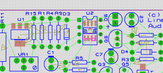
Jan, when you did the 8-pin composite footprint, did you put any tracks into the footprint itself?.
Yes I did, and when the moment comes to select the footprint elements by drawing a box around them and click Library|Make part, I can select which elements go into the footprint, pads, silk screen, any text and tracks and via's.
Took me some time to figure that out, I used to put in the tracks but forgot to select them and ended up with a footprint without tracks. That had me scratching my hair some ;-)
Jan
I am probably going OT here, but can you explain what's wrong if your software doesn't support a netlist? Or is it the other way round?
I've used Eagle, where one never needed to bother with netlists, and KiCAD, where it needs netlists. I haven't understood why software needs to be designed to use this intermediate representation called a netlist. My only hypothesis is that different groups of people wrote various schematic capture, sim, and PCB layout applications, and agreed to use a netlist as a common data format for making all of them work together. If a single team writes these applications, a netlist step is not needed.
If you have a layout suite that links to a schematic through a netlist, you cannot make any layout errors, because the program will alert you if you violate the schematic.
That means, that the only place you can make mistakes is in the schematic. But you are absolutely sure that the layout is exactly like the schematic connectivity.
I would never in my life use a layout toolset that doesn't use a schematic/netlist input, too error prone and slow because you have to do all the checking and verification against the schematic.
Another thing is that netlist-based layout normally shows the unrouted connectivity with thin lines from each pin on each part, called a ratsnest. A great time saver when placing parts for least track length.
Proteus also shows force vectors on each part showing where to move it for shortest tracks, but I don't know how that is in other packages. I would expect it to be fairly universal.
See attached: force vectors dark gray, ratsnest light green.
Jan
Attachments
I have a question, warned by a friend, about the use of triacs to power on/off and soft start. He worry about the buzz noise that can be induced by triacs at the primary of transformers because they begin to conduct only at some volts of the AC and he prefers mechanical relays here. What is your point of view and experience on this point ?
I agree with your friend. In my controlled switch-on/off I use a triac to do the switching, then wait a few cycles for the surge to die out, then bridge the triac with a relay. That helps to keep the relay healthy as it doesn't have to cope with very large rush-in currents. In switching off, I first make sure the triac is on, then open the relay, then turn off the triac.
Jan
I am sorry I wasn't clear earlier.If you have a layout suite that links to a schematic through a netlist, you cannot make any layout errors, because the program will alert you if you violate the schematic.
I agree with you 100%, the software needs to cross-verify that the PCB and schematic are in sync.
My point was: why do this sync'ing through a separate process step call netlist generation? In Eagle, the PCB layout program reads the schematic datafile directly and puts in a pile of components onto one corner of the PCB layout area for you to place. If you go back to the schematic later and add or delete parts there, the next time you open the PCB layout, you'll see the deleted parts missing and the new parts kept in a pile again on one side of the canvas. All earlier placed footprints, all nets and tracks, will be retained unchanged. If you delete a wire in the schematic, you come back to the PCB layout and you'll find the corresponding track deleted from the PCB (assuming you'd already laid the track earlier.)
What's best, you can actually add a component in the PCB and you'll go back to the schematic and find its symbol on one side of the schematic canvas.
All this is possible without you ever having to generate a netlist. I think this is very user friendly.
I was eluding to the fact that layout should have a netlist to follow, the format is not important, it could be buried in a binary, which is generated/maintained by a schematic tool. Of course you need a way to transfer information back and forth between sch and layout or there can be no synch.
It depends on if the symbol/footprint in layout has any net connectivity. If I add a heatsink, mounting holes etc to layout and they have no connectivity, it does not need to be shown in the schematic. In all my years doing layout, I have never had the need to add a footprint in layout that has connectivity, which I want annotated back to the schematic. If the new footprint has connectivity how are you supposed to do that in layout, i.e modify the nets list in layout, I do not think so. Like I said who is driving the bus and in control of the netlist?What's best, you can actually add a component in the PCB and you'll go back to the schematic and find its symbol on one side of the schematic canvas.
Last edited:
I do not have net list to use with Layout 6. I use a schematic that I draw first, and place the componets accordingly, I then mark the schematic with color pens as I go along. Then once done check and let others with the same interest, double check my work. Time consuming but workable.
I go very far back in doing this, Black Tape on clear acetate 4X layout out grid, I graduated to Red and Blue later. But anyone that wants to do this with a net list program, be my guest. I can not afford to pay for Eagle. Nice, but not in my budget or pirate thoughts.
I would hope for a Arduino controlled protection circuit, but dreaming is all I can do.
In my controlled switch-on/off I use a triac to do the switching, then wait a few cycles for the surge to die out, then bridge the triac with a relay. That helps to keep the relay healthy as it doesn't have to cope with very large rush-in currents. In switching off, I first make sure the triac is on, then open the relay, then turn off the triac.
You could connect some kind of impedance in series with the triac, to limit inrush current. Possibly a resistor, or a high current NTC thermistor (sold as "Inrush Current Limiter"), or something else. This reduces inrush which lengthens the lifetime of the power switch and the fuse. Later, when the relay is energized, the triac and the series impedance are shorted out as you say.
Here are a couple of scope photos of an audio power amplifier with an ICL but no bridging relay. Transformer primary current (i.e. mains current) is plotted vs time. It seems the 4X reduction of inrush amplitude is accompanied by a ~ 4X increase of inrush duration. Click on the images to remove distortion and to view full size.
Why not use KiCAD? It's rapidly becoming the Linux for electronic circuit design. Version 5 also includes a simulator which directly takes your schematic design and processes it, something which the likes of Eagle cannot do.I can not afford to pay for Eagle. Nice, but not in my budget or pirate thoughts.
I have just started using KiCAD on Linux after using Eagle for many years. I must say I'm impressed.
Both with the same opinion: I will do-it.I agree with your friend. In my controlled switch-on/off I use a triac to do the switching, then wait a few cycles for the surge to die out, then bridge the triac with a relay.
Power on in soft start with a triac in serial with a NTC/resistance then short both with a mechanical relay when big caps will be charged enough. And to power off: input signal off ->speaker relay off ->power mechanical relay off-> triac Off.
Ouf.
For what it's worth, I feel that mains inrush current limiter is best kept as a separate PCB, because it deals with mains voltages and probably needs to be positioned somewhere different from where the power amp PCBs will be.WHile we are now on the protection part of this project, I have several questions.
First, what features do-you like to see in this protection.
- Soft start ? (Better in a separate circuit that comes with linear PSU and exists yet in the SMPS ?)
- Silent stop ? (The main circuit is, on my point of view, fast enough to disconnect the speakers before any thump can be heard)
- Remote ?
- Temperature alarm ?
I feel the speaker protection circuit and the mains amp output short circuit protection circuit should be on the power amp PCB.
In fact I am probably a minority in one matter, but I feel that the primary smoothing capacitors of the main power supply to the amp should be on the same PCB as the power amp itself. I don't know any technical reason to keep them on separate PCBs, it's just for convenience in using reusable building blocks I guess.
Last edited:
Yes that is the ideal way. But sometimes you have to work with two systems. For instance, LTspice has no PCB part. It would be nice to generate a netlist from LTspice and open it in a PCB layout package.I am sorry I wasn't clear earlier. <snip>
BTW, even the integrated packages use a netlist between the parts of the suite. It's internally so normally you don't see it as a user.
Jan
Good argue.For what it's worth, I feel that mains inrush current limiter is best kept as a separate PCB, because it deals with mains voltages and probably needs to be positioned somewhere different from where the power amp PCBs will be.
Noted.I feel the speaker protection circuit and the mains amp output short circuit protection circuit should be on the power amp PCB.
Recap without touching the amp board ? Keep noisy lines far ?In fact I am probably a minority in one matter, but I feel that the primary smoothing capacitors of the main power supply to the amp should be on the same PCB as the power amp itself. I don't know any technical reason to keep them on separate PCBs, it's just for convenience in using reusable building blocks I guess.
No, I feel those can be addressed using good board layout. Also, one major area of noise are the rectifiers, and I can understand those being kept off-board, with their snubbing capacitors close to them.Recap without touching the amp board ? Keep noisy lines far ?
I think the bigger reason why people started using separate PSU boards was to share one PSU among multiple power amps. I usually land up using one PSU per channel, so maybe my thinking is driven by this.
You probably want to keep the main power supply caps also near the rectifiers on the PSU board, complemented with a smaller cap on the amp board. There are very high peak currents flowing from the rectifiers into the psu caps and you don't want that wiring all over the place. Keep it short and tight.
Jan
Jan
Yes, I too was thinking about the wisdom of my own opinions after writing that last post. I've seen caps put on the amp PCB in a few designs, but barring one or two, they've always been low power (< 50W) amps. So I guess if I do want to put them on the power amp PCB, then I should either put the rectifiers too next to them, or I should take special care in the layout to keep the caps a bit removed from other sensitive parts of the power amp.You probably want to keep the main power supply caps also near the rectifiers on the PSU board, complemented with a smaller cap on the amp board.
Thanks.
I believe the best solution with linear PSUs is: rectifier+Big caps as close to the transformer as possible with huge wires, and as far form the input stage of the amp as possible. And new low ESR caps on the amp board.I've seen caps put on the amp PCB in a few designs, but barring one or two, they've always been low power (< 50W) amps.
Those last ones will provide the amps during transients, and the resistance +inductance of the wires between the two cap banks help to filter parasitic noise due to the diodes switches.
On an "audiophile" point of view, I found that the most balanced combination was to use for each rail, single or double BIG caps near the rectifiers, and parallel >4 little ones (total 1/10 of the value of the big ones) on or close to the amp board. Adding one or more electrolytic film caps after them of 1/10 of the value of the previous, until you are able to add a film cap of, again 1/10 of the value of the previous one to filter HF and avoid resonances due to the inductance of the caps.
Playing with those values on the bench help to "balance" the tonal and dynamic character of the amps reproduction.
Last edited:
I can offer you this if you want. imo the smallest, cheapest that anyone can come up with (well at least me 🙂 and some would argue you do not need anything more but others well have their opinions, I use them all the time for testing....
I go back as far as home etching too, but you are using a computer now, so try to use the best tool that you can for the task. I understand that you think that you are productive but having/relying on people to verify connections is imo time that should be spent on getting the design right, the computer will verify your design rules and connections, makes life so much more productive. That's it I am done with my discussion on this topic, carry on.. p.s Jeff and Valery have a Arduino protection circuit avail, Valery was kind enough to give me his code. There is lots of help available, if you look around but to each their own.I do not have net list to use with Layout 6. I use a schematic that I draw first, and place the componets accordingly, I then mark the schematic with color pens as I go along. Then once done check and let others with the same interest, double check my work. Time consuming but workable.
I go very far back in doing this, Black Tape on clear acetate 4X layout out grid, I graduated to Red and Blue later. But anyone that wants to do this with a net list program, be my guest. I can not afford to pay for Eagle. Nice, but not in my budget or pirate thoughts.
I would hope for a Arduino controlled protection circuit, but dreaming is all I can do.
Attachments
I have a question as to the correctness and best practice of putting one or two 220uf or 1000uf capacitors right on top of the output transistors as close as possible to the lead of the transistor to have as much current available to the transistor at all times. Which is better, one 220uf or 2 1000uf? Thanks
I down loaded Kicad and watched some videos and will make a decision to use or not shortly. I am a cad fluent person, i.e. Autocad for many years, but any suggestions as to how to get on top of the learning curve are welcome. I am also learning Fusion 360, which is integrate-able with Eagle. So much to learn and so little time, and eyes and hands are getting old. Thanks
Is it permissible and ethical to integrate Valery code and hardware into this project? No one has said a word, when I asked about using OStripper's power system integration into this project, like on the GreenAmp... Thanks
Ask Valery, the general rule is you are allowed to use it for your own personal use, if you distribute, profit, you cross the line.
The problem with using a new cad tool, is your brain wants it to do as it was done before with the other tool, my advise, erase that part of your brain and continue 🙂 I know, easier said than done.
Is there a KiCAd thread?, I will look in the tools section. If there is not then users should start one up like the ltspice one. Focus on one tool, adding another one just adds confusion. Start small, do up a small schematic, gee a rectifier is an easy one, go to layout, generate your gerber, load up in jlcpcb to view the gerber and check that it loads properly. Follow the tutorials. ask ?'s in the KiCad thread or user group.
Last edited:
Something else to "sell" ?Jeff and Valery have a Arduino protection circuit avail, Valery was kind enough to give me his code. There is lots of help available, if you look around but to each their own.
The protection circuit itself, that will come once all its features will be discussed use the same comparator circuits integrated in the amp and used for DC servo and error correction. It is an intimate part of this project.
It will use a little two cents logic, will be faster and more sensible than anything else, and you want to bring us a computer and a program ?
Please, lets be serious and stay in topic.
- Home
- Amplifiers
- Solid State
- Pizzicato, a 200W low distortion CFA amplifier