These aberrations?
I'll leave it at that, because I won't take credit for Marcel's (huge amount of) work.
The point of these ABEC sims was to illustrate that 'bigger is better'.
Yes, the axial issues are better represented in those pics. What's the difference?
Do you have any ideas to help me produce a better final product?
I'm aiming to put the area between the top woofer and horn at ear level. The horn can be angled. Me sitting with feet flat, makes the enclosure about 47" tall
I just use stands - pretty easy solution.
So, they have designed a 50°x 60° horn... only to break the symmetry ?
Probably to narrow the beam (further) to increase output and reduce phase and other interference issues.
This horn was designed in order to cover the vocal range in stacked setups with BMS 4590 or 4592 coaxial.
Yes, the axial issues are better represented in those pics. What's the difference?
Size, the latter wg's mouth diameter is about 1/3 of the former.
I believe Marcel largely eliminated the abberations by placing a spherical cap in front of the wg in later sims.
I'll put your subjective opinion aside as its not the way I do things. As to changing the drivers, I don't make speakers anymore (haven't in years) , so that's not going to happen.
The subjective opinion wasn't intended to interfere with scientific design considerations 😉
Perhaps someone following this thread is interested in building a 2-way similar to the NS-15, or even bigger.
Last edited:
Probably to narrow the beam (further) to increase output and reduce phase and other interference issues.
Evidently this isn't correct, because the vertical coverage angle was increased by 10 degrees.
Anyway, for those interested, this is the thread. Most images have evaporated though.
What about Mr Don Keele's electro voice horns like HR 6040A or the famous HR 9040A?
These represent the acme of CD horn design IMHO.
Recently I have been studying the contours (there were different iterations) to determine whether they are suitable for a different application.
Comparison between HF10AK and TAD TD-2001 on a Markus Klug MK1010 (small multicel) and RCF H3709 (semi Altec/WE 32 clone).
5dB increments, but still...
(€137.15 = $153.82)
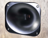
HF10AK, my favourite affordable Compression tweeter!
Size, the latter wg's mouth diameter is about 1/3 of the former.
I believe Marcel largely eliminated the abberations by placing a spherical cap in front of the wg in later sims.
Then I can agree with what you showed. I did not get the scale of the thing, but from what I saw this waveguide was 20" across. My NSW-15 is 18 and while the aberrations have diminished greatly, they have not disappeared. To do so at only 20" seems very surprising to me.
But your point is correct. As the mouth widens, the aberrations move lower in frequency. Hence at some size they will lie below the passband. Is that 20"? I don't know.
What do you mean by a spherical cap? The ideal is a flat piston.
These represent the acme of CD horn design IMHO.
What do you mean by "acme"? To me we have moved way past those older designs.

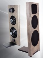
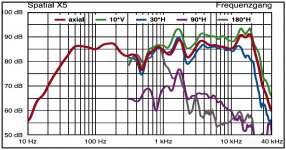
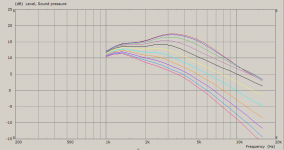
In the current issue of a magazine there is a test of a new Spatial Audio dipole speaker (No 5) using the HF10AK (it does at least look that way) on an XT1086. Unfortunately I couldn't find that model on the web though. It doesn't measure that nicely in this test but I assume this is due to a simplistic crossover. When I did some casual measurements of that driver/horn combination it looked much better.
The comp. driver appears to be the HF10AK, not only as regards the exterior of the driver, the response also shows the 'valley' between 1800 and 3500Hz.
12 and 15" are obviously Eminence Deltalites.
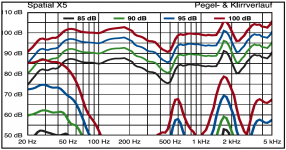
Overall the plots look rather miserable, but this may as well be contributed to the crossover, as you indicated.
Although the magazine acknowledges the mediocre measurement results, it apparently doesn't tamper the enthusiasm of the test panel.
FWIW: The Spatial X5 receives 63 out of 70 points for soundquality and 84 out of 100 overall.
Attachments

Last edited:
Gedlee, I just meant that, one of the drivers will be farthest away from being on axis....deciding which & how to locate the drivers. With TMM, the bottom woofer would likely be that driver. I can angle the horns. I am pondering how dramatic of an angle would still be acceptable given the 630hz xover and 15" woofer size....this is pertinent because of the desired near field listening position. Though not optimal, I must make the best of it.... Using a stand or floor standing, to put the 15"s closer to ear level raises the height of the horn.... I don't know how I'd like the tops to be coming from "above" so if I put the top of the top woofer at ~47" (basically ear level) that puts the center of the Horn 11.5 inches above and the center of the 15", ~8" below....and the center of the bottom 15" ~24" below that....I'll have to go back and read on our last discussion that lead me to feel comfortable with TMM.......If I did the upside down V shaped MTM with the woofers placed horizontal, from my reading, comb filtering will occur.....Read that as "will occur?" Looking for some confirmation I guess...I think someone already suggested that what I believe to be true on the matter, so......so, TMM it is I guess. I've seen upside down V shaped MTM with side by side woofers....Did no one tell them about the comb filtering?
At 10.5 ft3, floor standing is the only practical option to try and eat up some of the volume
H47" W25" D22"
Panel thickness 1"
Actually this is a perfect opportunity to clear up the idea of the formula for KA....I've basically adopted the formula from your paper on directivity, Gedlee, while others have accepted the approach of dividing speed of sound by diameter to discern a KA=2....what do you think of this?
Last edited:
do the big JBL studio monitors with the 2 woofers side by side (or Exclusive 2401) suffer from comb filtering issues?
EXCLUSIVE model2401twin
EXCLUSIVE model2401twin
"Don't confuse comb filtering with lobed response. Comb filtering occurs on the horizontal plane only when drivers are horizontally placed. Don't do that and there's no problem. Lobed response can be a problem with vertically aligned drivers at too close a listening position, but at usual distances wavefront integration is complete. Even Joe D'Appolito doesn't worry about keeping CTC to a wavelength anymore, and he should know.
I do question the MMTMM idea. The T might not keep up with all those Ms."
-billfitzmaurice
Midrange comb filtering -
Techtalk Speaker Building, Audio, Video Discussion Forum
I do question the MMTMM idea. The T might not keep up with all those Ms."
-billfitzmaurice
Midrange comb filtering -
Techtalk Speaker Building, Audio, Video Discussion Forum
an MMTMM like the PureAudioProject Quintet 15s ?
Quintet15, Wall of Sound Modular Open Baffle Speakers for Large Rooms – PureAudioProject
There honestly seems like there is no absolute right/wrongs when it comes to speaker designs... the more I read (and attempt to understand) the more confused I get.
Quintet15, Wall of Sound Modular Open Baffle Speakers for Large Rooms – PureAudioProject
There honestly seems like there is no absolute right/wrongs when it comes to speaker designs... the more I read (and attempt to understand) the more confused I get.
I'm playing with Xdir.... with no manual for goodness sake....I think driver distance is the spec for c-t-c.....seems that a TMM has polar issues before 630hz if spaced a few inches apart....I can't figure out this program completely so I might be using it wrong....I thought that as long as c-t-c was under the highest wavelength produced, the polar would be fine....
If I'm using Xdir correctly then a 2.5way or what I like to call a 2.2 system (mains plus subs on each stereo channel) would be the next obvious choice.
If I'm using Xdir correctly then a 2.5way or what I like to call a 2.2 system (mains plus subs on each stereo channel) would be the next obvious choice.
Last edited:
Then I can agree with what you showed. I did not get the scale of the thing, but from what I saw this waveguide was 20" across. My NSW-15 is 18 and while the aberrations have diminished greatly, they have not disappeared. To do so at only 20" seems very surprising to me.
But your point is correct. As the mouth widens, the aberrations move lower in frequency. Hence at some size they will lie below the passband. Is that 20"? I don't know.
What do you mean by a spherical cap? The ideal is a flat piston.
I am not sure, but I think Marcel somehow anticipated the disappearence of the aberrations with a sufficiently large mouth size and roundover.
The sims were posted in his local forum, so I have to rely on google translate for the interpretations of the comments.
This is the translated comment he posted along with the sims of the 52cm OSWG:
"Even with pure OSWG, excellent results can be achieved. As it is obvious from all this, the key is a sufficiently smooth outlet. Specifically, this is already 52 cm in diameter. Then even the circular symmetry will not have any negative effect (at least not visibly from these graphs).
Ie. if you do any horn, the bigger will always be better, and certainly not spare on a smooth outlet."
Outlet translates into "mouth roundover" I would think.
And later:
"The 52 cm was just a random number, of course related to how low it keeps the beam."
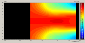
This is what he did (in ABEC) concering the 18cm OSWG, in order of appearance from left to right:
- flat 'cap'
- spherical cap
- SPL with spherical cap
- polar map with spherical cap.
Attachments


Last edited:
"CTC spacing is far less of a concern with a vertical alignment than horizontal. With what you're doing you mainly want to be sure that the woofers couple, and that means cone edge to cone edge must be less than a quarter wavelength. The difficulty that can arise in doing so is why many towers place dual woofers both at the bottom of the cab. Another reason for that configuration is that a woofer too close to the ceiling may result in boundary cancellation.
With the mids it would be best to have a CTC of a wavelength or less, but practically speaking the 1/4 wavelength edge to edge still applies, especially with regard to the distance between the mid drivers above and below the tweeter."
-billfitzmaurice
CTC spacing /comb filtering -
Techtalk Speaker Building, Audio, Video Discussion Forum
This kinda sheds some light but doesn't suggest yes or no about the lobing. Lobing on the vertical plane might not be a concern for some, and lobing on the horizontal plane is always more of an issue....
"Don't confuse comb filtering with lobed response. Comb filtering occurs on the horizontal plane only when drivers are horizontally placed. Don't do that and there's no problem. Lobed response can be a problem with vertically aligned drivers at too close a listening position, but at usual distances wavefront integration is complete. Even Joe D'Appolito doesn't worry about keeping CTC to a wavelength anymore, and he should know.
I do question the MMTMM idea. The T might not keep up with all those Ms."
-billfitzmaurice
Your T will definitely keep up with 2 Ms 🙂
- Home
- Loudspeakers
- Multi-Way
- Is it possible to cover the whole spectrum, high SPL, low distortion with a 2-way?