I tested ne555 protect circuit, only shirt circuit protection is not works otherwise all is working.is there any one tested this feature in this circuit
How did you that ?
Regards
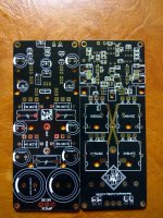
APEX SR200 RU EDITION.
You should put this fotos on SR200 place 🙂
Regards
..I built two of these PCB ax 14, both have the same problem, BIAS did not come to a standstill at zero !! I verified the operation P1 is ok, BD139 is on heat sink with insulation, the welds seem ok .... the PCB is very simple ... the margins of error are low .... I have not yet found the problem😕
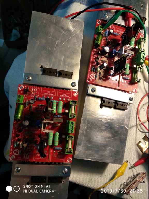
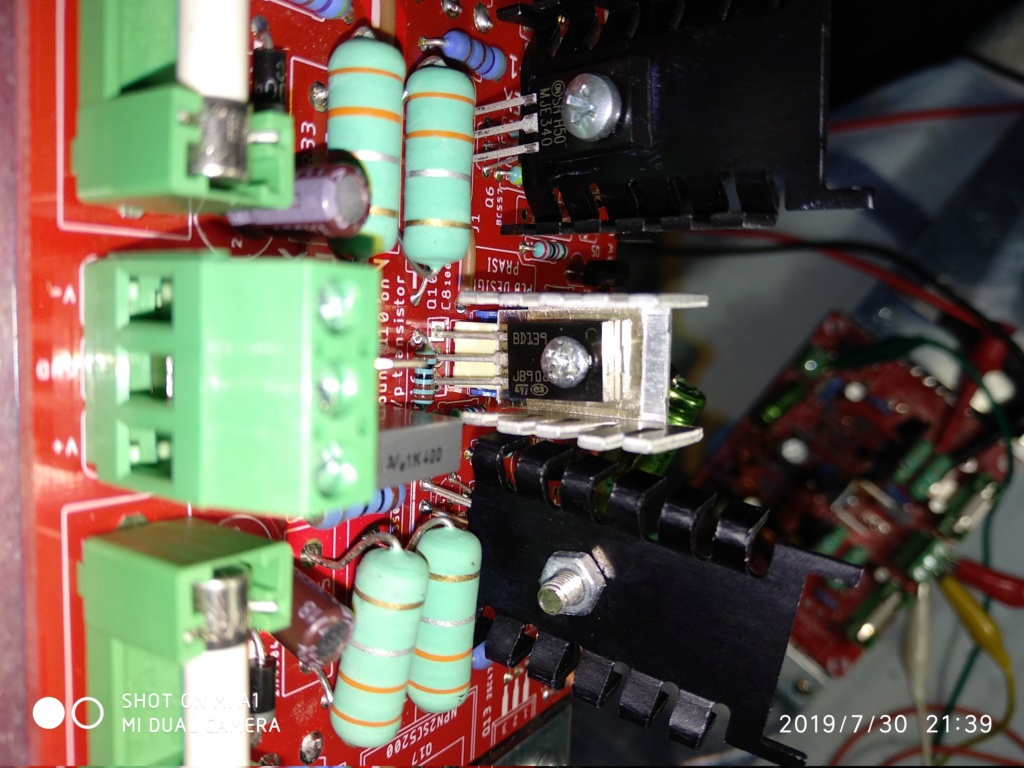

... I made measurements on this pcb, ... near the R16 I measure 0Volt .... All this because the BD139 is not placed on the heatsink of the transistors? strange
No, that is not the reason.
Please check your MJE's and BD139. Anyone could have blown or fake.
regards
Prasi
Please check your MJE's and BD139. Anyone could have blown or fake.
regards
Prasi
No, that is not the reason.
Please check your MJE's and BD139. Anyone could have blown or fake.
regards
Prasi
ok ... i'll check them
Hello
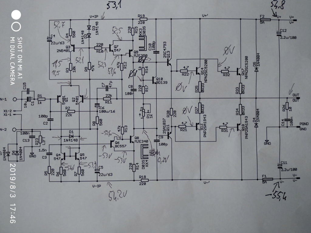
I see a raised voltage of -54V on Q4 & Q5 but these transistors are given for a voltage of 45V maximum on the transmitter ???
I see a raised voltage of -54V on Q4 & Q5 but these transistors are given for a voltage of 45V maximum on the transmitter ???
Hello
I see a raised voltage of -54V on Q4 & Q5 but these transistors are given for a voltage of 45V maximum on the transmitter ???
They are only passing 1V so they are fine. That -54V is measured to ground. C-E is only 1V.
ok ... i'll check them
Everything looks right up to q8 and q9. Make sure they are not faulty and check the pins are correct per the data sheet.
The base of Q11/Q13 should have around 1.1v (+&-).
Where did you buy the transistors from?
... I made measurements on this pcb, ... near the R16 I measure 0Volt .... All this because the BD139 is not placed on the heatsink of the transistors? strange
It looks as though you have a short to ground on the collectors of Q8 and Q9. Have you checked them for that?
OK, quick check in to make sure I am on track.
AX14, first channel hooked up and measured. All .33ohm resistors measuring 10-11mv as is the output. All settled down once the heatsink warmed up, sitting on a steady 36C, its a fairly substantial heatsink (as per pic).
So does this all seem to be within spec?
Thanks.
Edit, after 15-20 mins the heatsink has cooled to 33c.
Attachments
Last edited:
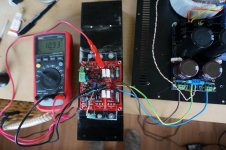
OK, quick check in to make sure I am on track.
AX14, first channel hooked up and measured. All .33ohm resistors measuring 10-11mv as is the output. All settled down once the heatsink warmed up, sitting on a steady 36C, its a fairly substantial heatsink (as per pic).
So does this all seem to be within spec?
Thanks.
Edit, after 15-20 mins the heatsink has cooled to 33c.
Seems right on. .011/.33=33mA. Looks good, keep the pics coming!
Nicely done Chrismum,
Looks fine. What about offset? (output to ground voltage).
Regards
Prasi
Looks fine. What about offset? (output to ground voltage).
Regards
Prasi
congratulations on successful build.
Enjoy your music and post some pics if you decide to put it in a case.
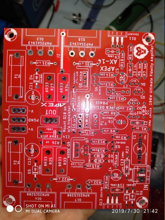
I see that you have populated C13 and the diodes D6/D7. Instead of C13 , you could populate R23, a 10 ohm 0.25W resistor.
Enjoy your music and post some pics if you decide to put it in a case.
I see that you have populated C13 and the diodes D6/D7. Instead of C13 , you could populate R23, a 10 ohm 0.25W resistor.
Last edited:
congratulations on successful build.
Enjoy your music and post some pics if you decide to put it in a case.
I see that you have populated C13 and the diodes D6/D7. Instead of C13 , you could populate R23, a 10 ohm 0.25W resistor.
Thanks Prasi.
R23 is soldered under the board bypassing C13 so both options there.
The heatsink its mounted on is part of the case which I got from Aliexpress. Will post some pics once its all together.
And thanks for the board design etc. and help during my build. The boards are great to work with, very clearly labeled and all components fit well. Nice straightforward build.
congratulations on successful build.
Enjoy your music and post some pics if you decide to put it in a case.
I see that you have populated C13 and the diodes D6/D7. Instead of C13 , you could populate R23, a 10 ohm 0.25W resistor.
Hi prasi, can use 10R 2W resistor for R23? The same which used for R26
Last edited:
- Home
- Amplifiers
- Solid State
- 100W Ultimate Fidelity Amplifier