The cure halves the gain.
Interstingly, gain is only marginally affected! The AC current from the input still goes through the 100R output resistor. Effectively the voltage gain at the transistor collectors goes up in the same way as the voltage is divided again.
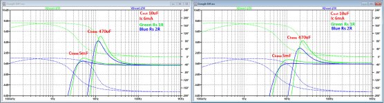
A quick check with LTSpice with additional 470R resistors confirmed this. Gain only marginally went down and the low frequency bump is cured.
Nice Bonsai!
Now if you remove the 2 large output caps, and put a single cap in the final output, you'll have the "James Chadwick" circuit. It does not exhibit the Leach/Lee common-base infrasonic anomaly.
Correct.
(NB The 'cure' does not halve the gain)
Did you use the exact values as in the circuit diagram of #712
and what value for Rs did you use ?
Hans
All values exactly the same and for Rs (5 Ohms and 10 Ohms)
The reason this works is that you are shifting the zero formed by C1 and R4 (and the counterpart on the other side C4 and R5) to c. 1.5Hz with the 220uF and 470 Ohm combo - i.e. its very low and out of the way. When the zero formed by these RC components is too high, its the same as raising the value of R8, which of course sets the gain higher.
When you don't have R4 or R5 in place, the zero formed with the output load resistor is much higher assuming it is 100 Ohms at > 7 Hz and you get the peaking behaviour because the gain is rising rapidly as the frequency goes down below this. If you leave R4 and R5 out you have to raise the value of R8 to > 500 Ohms to get rid of the bump (and pushing the zero down again to 1~2 Hz), but then the gain is too high - so you then have to use the Chadwick circuit divider trick to get it back to something useful.
When you don't have R4 or R5 in place, the zero formed with the output load resistor is much higher assuming it is 100 Ohms at > 7 Hz and you get the peaking behaviour because the gain is rising rapidly as the frequency goes down below this. If you leave R4 and R5 out you have to raise the value of R8 to > 500 Ohms to get rid of the bump (and pushing the zero down again to 1~2 Hz), but then the gain is too high - so you then have to use the Chadwick circuit divider trick to get it back to something useful.
Last edited:
Interstingly, gain is only marginally affected! The AC current from the input still goes through the 100R output resistor. Effectively the voltage gain at the transistor collectors goes up in the same way as the voltage is divided again.
A quick check with LTSpice with additional 470R resistors confirmed this. Gain only marginally went down and the low frequency bump is cured.
Yeah, that is correct for Rs=0 as shown, I stand corrected. There are other side effects though, like lowering the dynamic range.
Not the same story if Rs is considered, gain is no longer proportional to gm.
Thanks for this aboos. After 40 yrs, I now have an explanation for the good performance of 1980s Panasonic LoLeakage Aluminium caps and cr*p performance of Tantalums 😱If you look into datasheets for electrolytics/organics the specified the specified ESR can be very low for the organics but leakage current is at least 10-fold higher than for ordinary (low leakage) alu electrolytics.
Leakage currents are currents due to random defects in the microscopic thin alu-oxide layer. These then are healing again (by oxidation) by the flowing current. Being random in nature, this must result in noise currents. These processes are typically low frequency and thus should follow some 1/f***x function with x beeing highly dependant on technology and manufacturing conditions.
Same happens in Tantals and that's what Richard already reported in his original article as 'crackling' noise.
May I repeat my recommendation to LISTEN to your base caps in Duraglit. At its SOTA noise levels, the differences aren't Golden Pinnae ravings. Just increase the output resistor so you can hear the noise via your preferred playback chain.
_____________
Living in da bush these days, I'm unfamiliar with modern electrolytics ... apart from a frustrating episode with them dying repeatedly in computers a few years ago 😡
- How do you identify these EVIL organic electrolytics?
- Are Gerhad's "DigiKey 493-4582-1-ND Poly Alus" OK?
- What about syn08's "alu polymer caps PLG0E392MDO1 Nichicon | Capacitors | DigiKey"?
- Is it sufficient to look at leakage current of Aluminium electrolytics? I would personally listen to their noise for any important application
ZTX 851/951s Can we summarize experience with these as LN devices.
- H&H tested perhaps 100 and found them all good more than 2 yrs ago
- Wayne tested lots too and was happy about 2 yrs ago
- syn08 tested some recently and had to select for 1/f like I did circa 1979 for Zetex devices before I found the Hitachi devices.
Guru Wurcer, may I humbly ask what is GR noise?
_______________________
My thanks to Bonsai, Hans & the others trying to sort out the LF peaking in Duraglit
Last edited:
Guru Wurcer, may I humbly ask what is GR noise?
_______________________
My thanks to Bonsai, Hans & the others trying to sort out the LF peaking in Duraglit
https://pdfs.semanticscholar.org/a6e9/254a43991bf966e4065ad47dae7dde39c1fc.pdf
[*] How do you identify these EVIL organic electrolytics?
[*] Are Gerhad's "DigiKey 493-4582-1-ND Poly Alus" OK?
When I complained about OUTRAGEOUS 1/f**3 noise below 300 Hz, they obviously
are not ok. Did you read that text?
But they are not evil. When you just need few mOhms series resistance in a power
supply, they are a goto part. As a filter in a ultra low noise environment they may
have drawbacks. And they are easily identified. It's in the data sheet sheet that comes
with the order form.
And tantalums are not crap, especially wet ones.
It's just that you may not be prepared to pay $150 for one 4700U/25V.
Last edited:
Digging a bit deeper into the LF bump problem, I tried to find the pro's and con's of various measures.
Starting with the damping as suggested by Bonsai:
It has no impact on noise and some minor effect on THD and Gain, nothing to worry about,
Damping is indeed applied, but for a Duraglit amp that has just enough dynamic range without damping, it seems rather unacceptable that DR may be reduced up to 10dB depending on the setting.
So when using this damping by placing resistors in the output line, this has to be done with great care.
Another way of getting rid of the LF bump is to reduce the output cap from 220uF to a much lower value like somewhere between 10uF and 22uF.
No reduction in DR will happen and no tuning will have to be done when using large caps for the base voltages of both transistors.
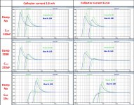
In the Image below, the left column applies when using a collector current of 2.8 mA, the right column for 6mA to reduce noise if needed.
Simulation is done for a 5R (in green) and a 10R (in bue) Cart, having an output of 0.5mV@5cm/sec@1kHz, thus needing a Headamp with a gain of 10.
The three rows are resp. for 1) "no damping+220uF", 2) "220R damping+220uF" and 3) "no damping and 10uF".
For each individual situation, the effect of using a 0.5mF or a 5mF Cap is shown.
The effect of a larger Cap is mainly shifting the Bump to the "left", as can be well seen in the various plots.
I did the same simulations for a 2R and a 5R 0.25mV Cart, needing a gain of 20, and for a 1R and 2R 0.1mV Cart needing a gain of 50.
Results were quite comparable with the above.
So to conclude it can be destilated from the findings, that the larger Rs, the lesser the Bump problem, but I would strongly advise to always substantially reduce the two 220uF output Caps.
Hans
Starting with the damping as suggested by Bonsai:
It has no impact on noise and some minor effect on THD and Gain, nothing to worry about,
Damping is indeed applied, but for a Duraglit amp that has just enough dynamic range without damping, it seems rather unacceptable that DR may be reduced up to 10dB depending on the setting.
So when using this damping by placing resistors in the output line, this has to be done with great care.
Another way of getting rid of the LF bump is to reduce the output cap from 220uF to a much lower value like somewhere between 10uF and 22uF.
No reduction in DR will happen and no tuning will have to be done when using large caps for the base voltages of both transistors.
In the Image below, the left column applies when using a collector current of 2.8 mA, the right column for 6mA to reduce noise if needed.
Simulation is done for a 5R (in green) and a 10R (in bue) Cart, having an output of 0.5mV@5cm/sec@1kHz, thus needing a Headamp with a gain of 10.
The three rows are resp. for 1) "no damping+220uF", 2) "220R damping+220uF" and 3) "no damping and 10uF".
For each individual situation, the effect of using a 0.5mF or a 5mF Cap is shown.
The effect of a larger Cap is mainly shifting the Bump to the "left", as can be well seen in the various plots.
I did the same simulations for a 2R and a 5R 0.25mV Cart, needing a gain of 20, and for a 1R and 2R 0.1mV Cart needing a gain of 50.
Results were quite comparable with the above.
So to conclude it can be destilated from the findings, that the larger Rs, the lesser the Bump problem, but I would strongly advise to always substantially reduce the two 220uF output Caps.
Hans
Attachments
Last edited:
What load resistor have you used on the output Hans? 100 Ohms?
I have set the gain to exactly 20dB as needed for a 0.5 mV Cart, see text and images.
So for the four variations of Rs and collector current I have used 4 different load resistors to get exactly this 20dB gain, resp. 99, 162, 73 and 127 Ohm.
Hans
Just stumbled across some Zetex/Diode, Inc transistors with healthy hfe.
BF=1100. There are more.
.MODEL ZXTN07012EFF NPN IS=1.7p NF=1 BF=1100 IKF=5 VAF=25 ISE=3E-13 NE=1.43 NR=1 BR=470 IKR=1 VAR=6.5 ISC=1.2p NC=1.5 RB=0.1 RE=0.03 RC=0.0097 RCO=0.2 GAMMA=10E-10 CJC=106p MJC=0.33 VJC=0.55 CJE=285p MJE=0.41 VJE=0.80 TF=0.4n TR=1.3n XTB=1.4 TRC1=0.003 TRB1=0.003 TRE1=0.003 QUASIMOD=1 Vceo=12 Icrating=4.5 mfg=Zetex
I was really looking for some DPAK to relief op amps of unnecessary heat (high VCC)
And the only supplier is Aliexpress ?? 😀Just stumbled across some Zetex/Diode, Inc transistors with healthy hfe.
BF=1100. There are more.
.MODEL ZXTN07012EFF NPN IS=1.7p NF=1 BF=1100 IKF=5 VAF=25 ISE=3E-13 NE=1.43 NR=1 BR=470 IKR=1 VAR=6.5 ISC=1.2p NC=1.5 RB=0.1 RE=0.03 RC=0.0097 RCO=0.2 GAMMA=10E-10 CJC=106p MJC=0.33 VJC=0.55 CJE=285p MJE=0.41 VJE=0.80 TF=0.4n TR=1.3n XTB=1.4 TRC1=0.003 TRB1=0.003 TRE1=0.003 QUASIMOD=1 Vceo=12 Icrating=4.5 mfg=Zetex
I was really looking for some DPAK to relief op amps of unnecessary heat (high VCC)
< ZXTN07012EFFTA Diodes Incorporated | Diskrete Halbleiterprodukte | DigiKey >
Probably Mouser, too.
🙂 Gerhard
Probably Mouser, too.
🙂 Gerhard
Last edited:
< ZXTN07012EFFTA Diodes Incorporated | Diskrete Halbleiterprodukte | DigiKey >
Probably Mouser, too.
🙂 Gerhard
Interesting transistor with a PNP complement although again with an unrealistic Rb = 0R1.
Once Bill will be ready to send me his “Wayne” design, I could compare these trannies with the ZTX pair.
Hans
Last edited:
This is a similar simulation as #731, but now for 0.1mV output 1R and 2R Caps, the Headamp thus needing a gain of 50.
Because these Carts demand a very low amp noise, I have simulated this time for collector currents of 6mA and 12mA.
The image below is just for the version with 10uF output caps and no damping, just like the lower version of the three in #731.
Again, using 5mF instead of 470uF base Caps in combination with 10uF output Caps, gives a perfect FR.
Hans
P.S. Correction: In the right plot is written Ic 6mA, this should be 12mA.
The left one is correct with 6mA.
Attachments
Last edited:
Just stumbled across some Zetex/Diode, Inc transistors with healthy hfe.
BF=1100. There are more.
Interesting high beta is usually a counter indicator for low rbb but this device also has very low Vcesat.
The 60C/W for SOT23 is interesting also since the pads look like standard size, seems to almost defy physics. Notes say big 2oz copper land needed but I'm used to big metal area on back of package for that.
Hans, on the Hawking, if you run your sims but look at the collector voltage of the transistors before the DC blocking caps (with or without dampers) what are you getting? This is with the 10uF capacitors
- Home
- Source & Line
- Analogue Source
- Richard Lee's Ultra low Noise MC Head Amp