Idem.I tried your models but was having trouble getting LTspice to accept them. Do you have an example schematic? Ian Hegglun's VDMOS models gave about 50% worse distortion and the compensation needed re-balancing. Still OK in the scheme of things.
Small adjustments on the compensation caps value will have, of course, to be done on the bench. Because the phases turns are in the 1-10MHz region, it will
depend IRL of the board parasitic elements.
Thanks for your nice words. Art work is excessive, don't you think ?Good job Tryphon Tournesol
Great design. Am noting your not into input caps and your design could be from the same family or a distant cousin of an amplifier am investigating. I hope your into wine tasting. There are some parameters that am investigating. So if it would tickle your bone would you cobble up the FS amplifier at Amplifiers | Harrison Audio Labs and provide a critical listening test 🙂 in comparison to your art work.
Cheers again
Aska has answered exactly how i should had done. Apart a big difference: CFA VS VFA. Your amp looks, indeed, like a nice one.
Exicons are rated at 200V and 16A. Designs were bridged.
I tried your models but was having trouble getting LTspice to accept them. Do you have an example schematic? Ian Hegglun's VDMOS models gave about 50% worse distortion and the compensation needed re-balancing. Still OK in the scheme of things.
Bridge mode is no saving in power dissipation. It halves the voltages but doubles the currents.
Those Exicons are simply two "regular" devices in the same case. The reason you need so many laterals in parallel is not exceeding the maximum current, but the fact that for laterals the transconductance is dropping quickly at high drain currents. Transconductance is low, anyway, 1S or 2S for those double Exicons. A normal IRF240 vertical mosfet starts from 6S and does not drop quickly at high drain current.
Sorry, I am not a LTSpice user, but the models are fairly standard to integrate. Not sure what problems you have with them, but a schematic won't help, anyway.
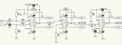
Attached, the last sim file.
I really need help to simulate this. When I run the Servo and error correction alone: no prob.
When I run the amp alone: no problem neither. Together, it turns round and round during hours with no error, and I alway finish to give-it up with "core hot".
Really, I'm definitely not a "sim" guy ;-)
Working blind, without listening to anything with a program that rely on fake models ... Is-it serious ?
Is the solution should be to make a "sub" with this OPAMPs part ?
Another question, is there is a way to "comment" a part of a circuit (deactivate the calculations of this part) without removing them completely from the schematic ?
About input caps, it seems to me that, comparing a good film one with a straight wire do not make a big difference on the listening experience, and not in a way (if any) that can worsen the sound.
On the other side, as the polarisation of all the power amp depend on what is presented in front of the bases of the input transistors, it seems careful not to avoid them. As well as a separation serial input resistance.
Attachments
Experimenting with different output devices to see if the design falls apart. Ian Hegglun's models are used for the MOSFETs. These models are more complex than the Cordell laterals. Still seems unlikely.
8 ohm 100mA quiescent
1KHz 0.000033%
20KHz 0.00079%
1MHz 1.32%
4 ohm 100mA quiescent
1KHz 0.000092%
20KHz 0.0019%
1MHz 2.35%
8 ohm 33mA quiescent
1KHz 0.00011%
20KHz 0.0022%
1MHz 1.48%
4 ohm 33mA quiescent
1KHz 0.0002%
20KHz 0.0041%
1MHz 2.79%
The BJT is less compatible. Output device models are from Keantoken.
8 ohm 32mA quiescent
1KHz 0.01%
20KHz 0.01%
600KHz 0.94%
4 ohm 32mA quiescent
1KHz 0.036%
20KHz 0.037%
600KHz 1.8%
Attachments
Together, it turns round and round during hours with no error, and I alway finish to give-it up with "core hot".
Professor, have you thought about asking in the Yahoo LTspice user group? They are the experts on this, having a direct line to the LTspice development team.
Then again, I have seen some sims run for a day, so maybe just let it run overnight, using shortest time you can. Or replace the servo with a VCVS instead of the opamp. We DO know an opamp works ;-)
Be creative!
Jan
I will. I was just hoping to get answers form the LTSPICE experts of the forum. I have let this run for > 7 hours.Professor, have you thought about asking in the Yahoo LTspice user group? They are the experts on this, having a direct line to the LTspice development team.
[EDIT] Found the problem, A LTSPICE bug: it has disconnected a wire in a place I did not changed anything and did not noticed, thanks.
Spladski, I don't think it is a good thing to run two separate versions of this amp. We have to decide together which one has to be choosed and continue to work together at this point. The main difference is your use of two drivers instead of 1. On my side, I don't find a major advantage of it, keeping-it as simple as possible. See my last sim without error correction. We have to agree too on witch model to use for Power FETS: I will follow your advice. May we discuss those points, work together in adding a definitive error correction and servo with it (It will come with a protection) the begin to look at get a printed board design ? (PS I don't had answer to my last private message to you)
Attachments
The BJT is less compatible. Output device models are from Keantoken. <snip>
Triple darlington output stage results much better distortion. And single driver pair, such 2SC4883/2SA1859 can push 4 pairs of output devices.
Sajti
Satji, I insist to ask everybody who feel like participating to this project to stay 'practical'. I mean proposing a schematic and the simulation results.Triple darlington output stage results much better distortion. And single driver pair, such 2SC4883/2SA1859 can push 4 pairs of output devices.
This project is based on inclusive compensation, and any added pole in the feedback loop can lead to problems.
The exercise I just performed supports your view that a single driver will be fine. It is still a sandbox and I am searching for a 1Mhz solution and also validation that the design will deliver in practice. My investigations can continue in parallel. I am a R&D person and like to know the four corners of the envelope before signing off. When people come to me with issues I can normally give a one line solution. They leave with a puzzled look on their face because they don't know I have already done the homework.
I haven't seen a PM needs response.
I haven't seen a PM needs response.
Here we are:
Attachments
Last edited:
This is a philosophical question. When we are not able to hear, for most of us, any 20KHz signal at full power, how can-we expect to hear harmonics of it at <-90dB ?1k thd is not interesting. go below 1ppm at 20k 🙂
Anyway, to answer to your question simulated HD at 20KHz, +-50V, 0.000184% . Main harmonic (3) at at -120dB.
Pure fantasy, anyway ... simulations ;-)
Edit: Aligning the phases at 20kHz in the err.comparator, it can go down to 0.000131%
Attachments
Last edited:
Are-you considering a PCB design ?Which devices need to be thermal coupled on the pcb?
Why else would I ask for the information, maybe but I might make provisions to use either of the transistors that I asked about before. In all the locations.
Thanks a lot Krisfr. Nice to see-you on this.Why else would I ask for the information, maybe but I might make provisions to use either of the transistors that I asked about before. In all the locations.
About your thermal question, It should be good to get Q2 & Q6 and Q1 & Q5 for offset, but as we have a servo, I don't know if it is an absolute requisite.
Some tips: feedback resistances R11 & R34 have to be through holes. MUNDORF ?
The feedback line that come to R11 has to be took at the R2/L1 point directly to the R11, not connected to anything else before this point, and as short as possible. No inductive resistance. Q8, Q13, Q4, Q14 have to be mounted on a radiator. May-be on an aluminium or copper plate that cross the PCB, bringing a thermal coupling as well ?
I propose R3 to be an adjustable, just the time to adjust the quiescent on the Bench. Once done, to be replaced by 2 // fixed resistances selected to make the same value ?
Do-you think the servo and error correction has to be mounted on the main PCB or in a separate one ? It will come with 2/3 comparators, a transistor, a static or/and mechanical relay.
About tuning the amp on the bench, the connections Servo out/Err-corr-Out has to be cut from the Opamps out, and connected to the ground, the time to tune the offset. When this is done, they have to be reconnected, and R57 adjustment has to be made, looking at the U3 out, to minimize the level. The perfect point is succeed when the signal is 90° out of phase from the input signal.
Some resistance has to be more than 1/4 Watt, not indicated yet on the schematic.
What else ?
Oh, yes, of course, the gate paths between the driver and the Power FETs devices as short as possible (to avoid parasitic inductances)
Last edited:
Great starting point information. I will prepare aSplan schematic and BOM, and once agreed upon, go ahead with the topology layout.
Where will the additional parts go? Also how do you want to make the 12 volts, with resistor zener and cap?Do-you think the servo and error correction has to be mounted on the main PCB or in a separate one? <snip>
Attachments
Last edited:
- Home
- Amplifiers
- Solid State
- Pizzicato, a 200W low distortion CFA amplifier